


 Abstract
 HTML
HTML Reference
 Related
 PDF
PDF


HTML
-
The interaction of neutrinos with matter is extremely weak, hence they easily penetrate celestial bodies. Determining the neutrino spectrum and flavor can shed light on their production reaction and environment. They are thus ideal probes for the Earth and Sun. Geoneutrinos are primarily generated by three types of long-lived radioactive isotopes, potassium-40 (
$ ^{\rm{40}} {\rm{K}}$ ), uranium-238 ($ ^{\rm{238}} {\rm{U}}$ ), and thorium-232 ($ ^{\rm{232}} {\rm{Th}}$ ). Their origin, composition, and distribution are highly interesting questions in geoscience. They can aid in the discovery of the physical and chemical structure of the Earth and even reveal its evolution.The KamLAND [1–4] and Borexino [5–7] experiments have made pioneering contributions to the discovery of geoneutrinos. Their detection is achieved by detecting inverse-beta-decay (IBD) signals in liquid-scintillator detectors. An IBD signal consists of a prompt positron signal and a delayed neutron-capture signal, and the prompt-delay-coincidence provides a clear signature of the interaction. The IBD cross-section is relatively high. The energy threshold for the reaction is 1.8 MeV, and only
$ ^{\rm{232}} {\rm{Th}}$ and$ ^{\rm{238}} {\rm{U}}$ geoneutrinos are accessible. Almost no directional information can be extracted for the initial neutrinos [8].Neutrinos originating in the mantle have a direct connection with the power that drives plate tectonics and mantle convection [9, 10]. However, the measurements on mantle geoneutrinos rely heavily on crust geoneutrino predictions. Consequently, the mantle component still has considerable uncertainty. In Ref. [11], Tanaka and Watanabe proposed to use a 6Li-load liquid scintillator to extract directional information on U and Th neutrinos using the IBD process and even image the Earth’s interior.
The K element is more mysterious than U and Th.
$ ^{\rm{40}} {\rm{K}}$ decays contribute roughly to 1/3 of the radiogenic heat of the Earth, however no experimental$ ^{\rm{40}} {\rm{K}}$ neutrino result has been reported to date. Because K is a volatile element, precipitating it into typical mineral phases is more difficult than for U or Th. Measuring the flux of$ ^{\rm{40}} {\rm{K}}$ neutrinos versus$ ^{\rm{238}} {\rm{U}}$ and$ ^{\rm{232}} {\rm{Th}}$ neutrinos can offer input to the understanding the formation process of the Earth [12]. The model of$ ^{\rm{40}} {\rm{K}}$ and$ ^{\rm{40}}{\rm{Ar}} $ in the air and the Earth also indicates the enriched and depleted mantle structure [13]. In [14], Leyton, Dye, and Monroe proposed to use directional neutrino detectors, like noble-gas time-projection chambers, to explore various geoneutrino components.Notably, thus far, the liquid scintillator detector of Borexino is the only one that achieved sub-MeV neutrino spectroscopy, where both large target mass and low background are realized. Solar neutrinos are detected through neutrino-electron scattering,
$ \nu+e^- \rightarrow \nu+e^-, $

(1) which has no theoretical threshold. There is a strong correlation between the initial neutrino and scattered electron direction, especially after imposing a requirement on the kinetic energy of the recoiling electron. In this study, we consider introducing directionality to the conventional liquid scintillator detector to suppress the intrinsic solar neutrino background and detect the
$ ^{\rm{40}} {\rm{K}}$ geoneutrinos.Because of the long emission time constant of scintillation radiation, the new type of liquid-scintillator Cherenkov neutrino detectors [15–17] can identify the small prompt Cherenkov radiation within the large amount of slow scintillation light. This unique feature can provide not only the reconstruction of both direction and energy, which has never been achieved in conventional liquid scintillation neutrino detectors, but also particle identification [18]. We consider two schemes for the liquid-scintillator Cherenkov neutrino detector. The first approach is to use a fast, high-light-yield liquid scintillator and fast photon detectors. In this case, the light yield can reach 10,000 photons per MeV with an emission time constant of a few nanoseconds, which is much longer than several picoseconds of timing precision of the photon detectors. The recent experimental development for this approach can be found in Refs. [19–21]. The second approach is to use a slow liquid scintillator and photomultiplier tubes (PMTs). The PMTs usually have a timing precision of about one nanosecond, while the emission time constant for the slow liquid scintillator is much longer, for example, 20 nanoseconds [22–24].
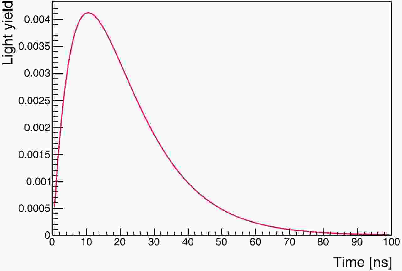
In this study, we focus on the latter scheme. We adopted the parameter set for pure linear alkylbenzene (LAB) [22] as a slow liquid-scintillator candidate, which is most favorable for the Cherenkov separation. The light yield is 2530 photons/MeV, and the emission rise and decay time constants are 12.2 ns and 35.4 ns, respectively. The time profile is shown in Fig. 1. The Cherenkov threshold is 0.178 MeV, assuming the refractive index of the liquid to be 1.49 [25].
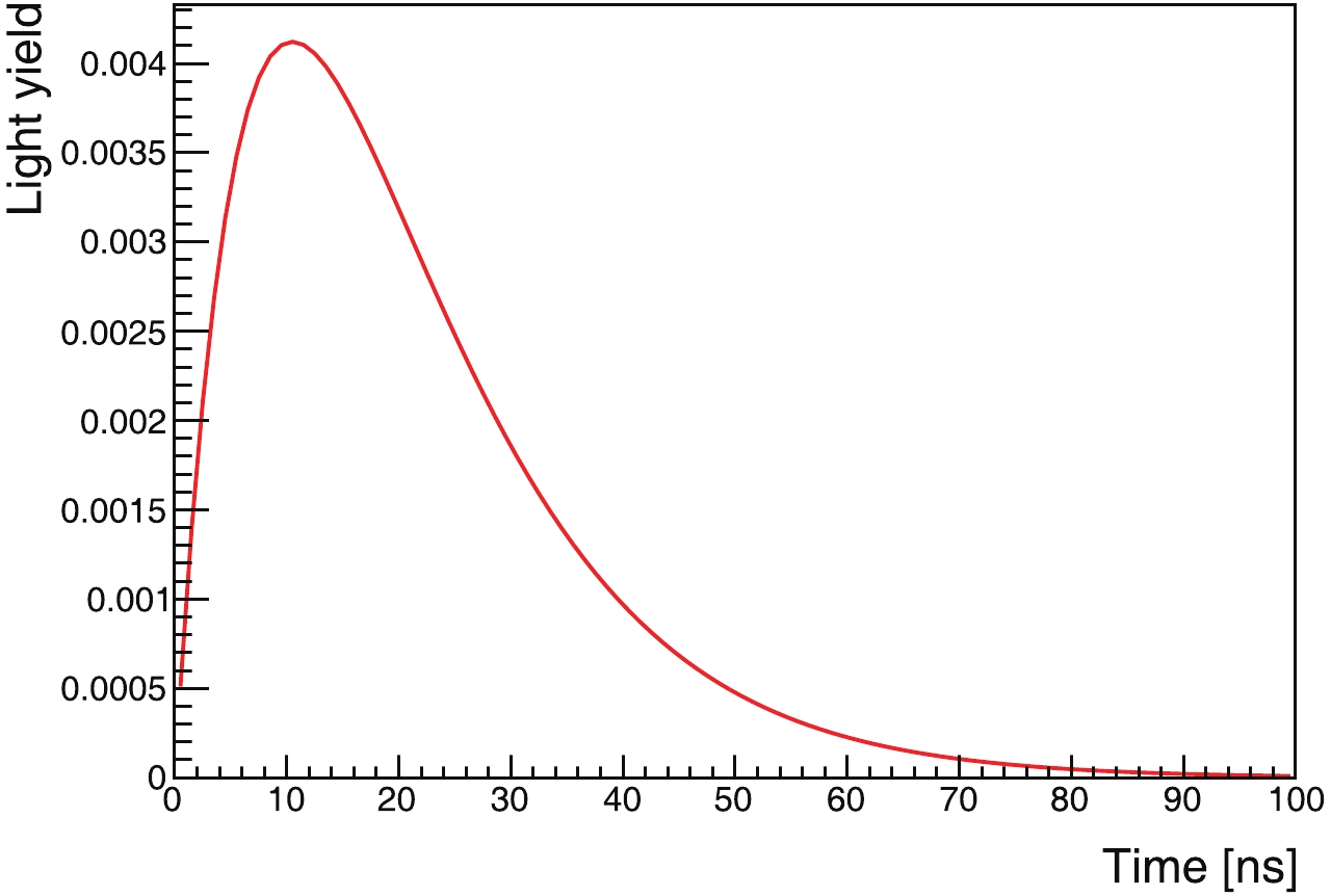
Figure 1. (color online) Normalized time profile of scintillation light emitted by slow liquid scintillator, LAB [22].
-
We consider an ideal terrestrial detector, located at the Earth’s equator, rotating along with the Earth. We define the solar z-axis,
$ z_{\odot} $ , from the Sun to the Earth, and an Earth z-axis,$ z_{\oplus} $ , from the center of the Earth to the detector (Fig. 2). Correspondingly, we define the angle between the recoiling electron and$ z_{\odot} $ as$ \theta_{\odot} $ , and the angle with$ z_{\oplus} $ as$ \theta_{\oplus} $ . Geoneutrinos and solar neutrinos are generated, and the kinetic energies of the recoiling electrons are recorded. With a cut on the recoiling electron kinetic energy at 0.7 MeV, the distributions of$ \cos\theta_{\odot} $ and$ \cos\theta_{\oplus} $ for the remaining neutrinos are shown in Fig. 3. The geoneutrinos (crust and mantle) are clearly separated from the solar-neutrino background. Since the energy range of the$ ^{\rm{40}} {\rm{K}}$ neutrinos is distinguishable from those of the$ ^{\rm{232}} {\rm{Th}}$ and$ ^{\rm{238}} {\rm{U}}$ neutrinos, there is a possibility to detect the$ ^{\rm{40}} {\rm{K}}$ component. Next, we consider a real detector.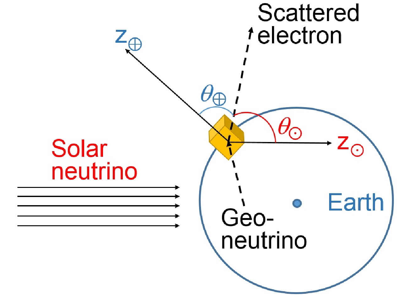
Figure 2. (color online) Definitions of
$ z_{\odot}, z_{\oplus}, \theta_{\odot}$ , and$ \theta_{\oplus}$ . The yellow cube represents the neutrino detector.
Figure 3. (color online) Theoretical distributions of
$ \cos\theta_{\odot}$ and$ \cos\theta_{\oplus}$ for solar, crust, and mantle neutrinos when the kinetic energies of the recoiling electrons are required to exceed 0.7 MeV. -
We adopted the detector scheme [26] shown in Fig. 4. The slow liquid scintillator, which is contained in a transparent container, is in the center, and it is surrounded by a non-scintillating material, such as water or mineral oil. The PMTs are installed with all photocathodes facing inward, forming a large spherical array. The PMTs are all immersed in the water or oil. The water behind the PMTs also serves as a veto layer, shielding the detector from radioactivities like betas, gammas, neutrons, and cosmic-ray muons. The number of signals is directly proportional to the target mass, and due to the required low-background rate, only the central region of the liquid scintillator, known as the fiducial volume, is accepted for signal detection.
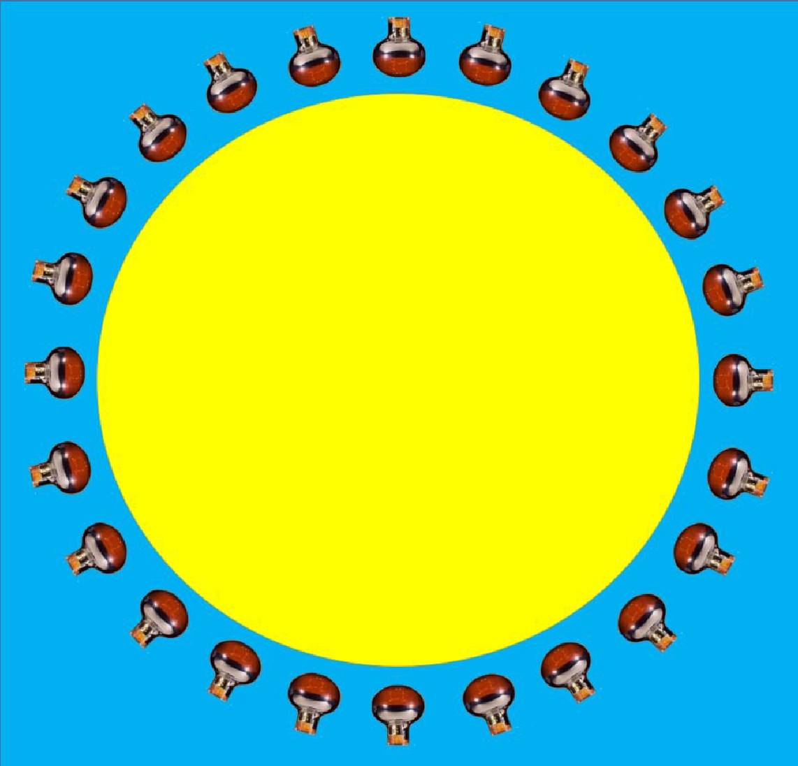
Figure 4. (color online) Detector concept. Inside to outside: slow liquid scintillator (yellow), water (blue), PMT, and water.
The simulations of solar-neutrino generation, geo-neutrino generation, and neutrino-electron scattering are described in Appendix A, Appendix B, and Appendix C, respectively. Recoil electrons are simulated using Geant4 [27–29] including all possible electromagnetic processes. Because of multiple scattering, the initial direction of the electron is smeared out. Some electrons eventually turn back when they are close to stopping.
Both Cherenkov and scintillation light emissions are handled by Geant4; however, the production of scintillation light is customized according to LAB measurement [22].
All optical photons are recorded and undergo empirical simulations [26, 30], as the attenuation length of optical photons still requires more experimental research [22], and the target mass or volume is a parameter we want to test. The limited PMT photocathode coverage and photon attenuation and scattering will cause efficiency loss, hence we assume that practically only 66.7% (2/3) of the photons can reach the PMTs. The quantum efficiency of a PMT is assumed to be 30% for all photons within the range [300, 550] nm and to be zero for the rest, which is motivated by the high quantum efficiency of PMTs, according to Ref. [31]. In summary, the total efficiency for generating photoelectrons, PE, is 20% for photons within the range [300, 550] nm and zero outside of this wavelength range.
-
From the simulation, we can determine the average energy scale, i.e., the number of PE per MeV, and thus the total number of detected PEs for each event is scaled to the detected energy. The detected-energy spectra of solar- and geo-neutrinos are shown in Fig. 5 and Fig. 6, respectively.
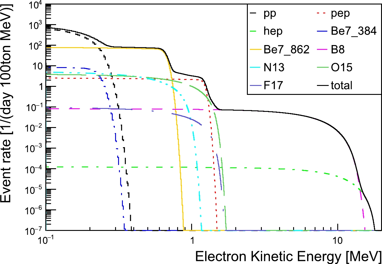
Figure 5. (color online) Detected kinetic-energy spectra of recoiling electrons produced by solar neutrinos in simulation.
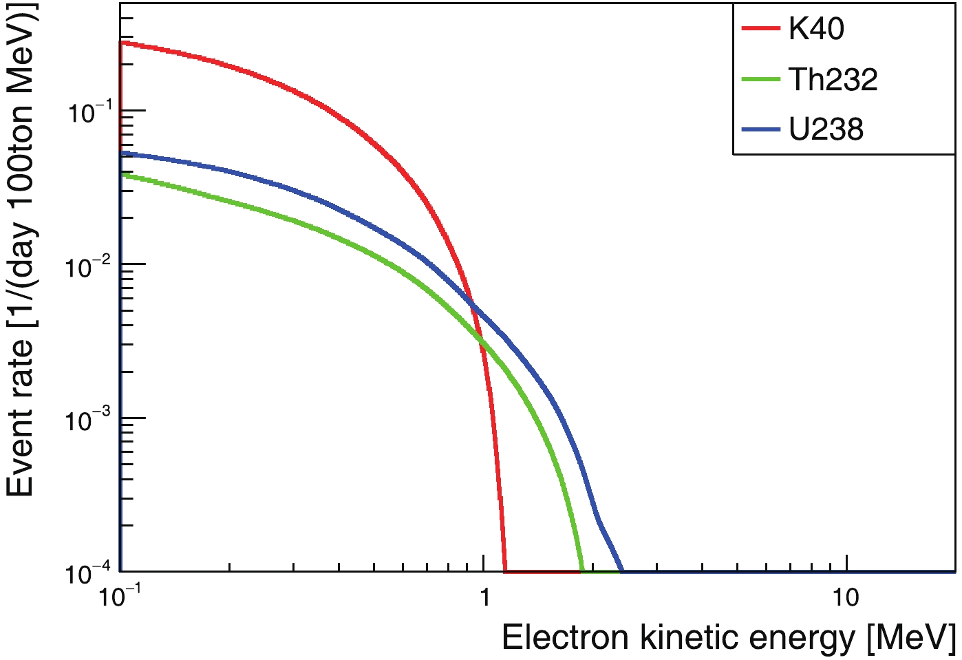
Figure 6. (color online) Detected kinetic-energy spectra of recoiling electrons produced by geoneutrinos in simulation.
We use a weighted-center method to reconstruct the direction of the recoiling electrons,
$ \vec{R} $ . The formula is$ \vec{R} = \frac{1}{N_{\rm{PE}}}\sum\limits_{i = 1}^{N_{\rm{PE}}} \vec{r}_{i}, $

(2) where
$ \vec{r}_{i} $ is the direction of each photoelectron, and$ N_{\rm{PE}} $ is the number of photoelectrons.We attempted three groups of photons. In Case (1), we use all Cherenkov photons to study the best case and understand the scattering of electrons in the liquid scintillator. In Case (2), we apply the 20% efficiency cut, as described in Section 1.2. We use this study to understand the results with Cherenkov photons only. In Case (3), we tested a more realistic case, where the detection efficiency is considered, and the photoelectrons from the first two ns of scintillation radiation are introduced.
The angular response is plotted in Fig. 7 for electrons with kinetic energies in the range of [0.5, 2] MeV, where we show the cosine of the angle between the reconstructed direction and the initial electron direction for all three cases. For case (1), the angular resolution with 99% coverage is 116 degrees, and it is 124 and 125 degrees for the second and third cases, respectively. Comparing Case (1) with (2), which includes the 20% efficiency cut, the latter does not show significant degradation of the reconstructed angular distribution. The dominant factor affecting the performance of directional reconstruction is electron scattering in the liquid scintillator. After further introducing the scintillation photons as the background in Case (3), we find that the angular resolution is slightly worse than for Case (2). In the rest of this paper, we focus on Case (3), which is the more realistic one.
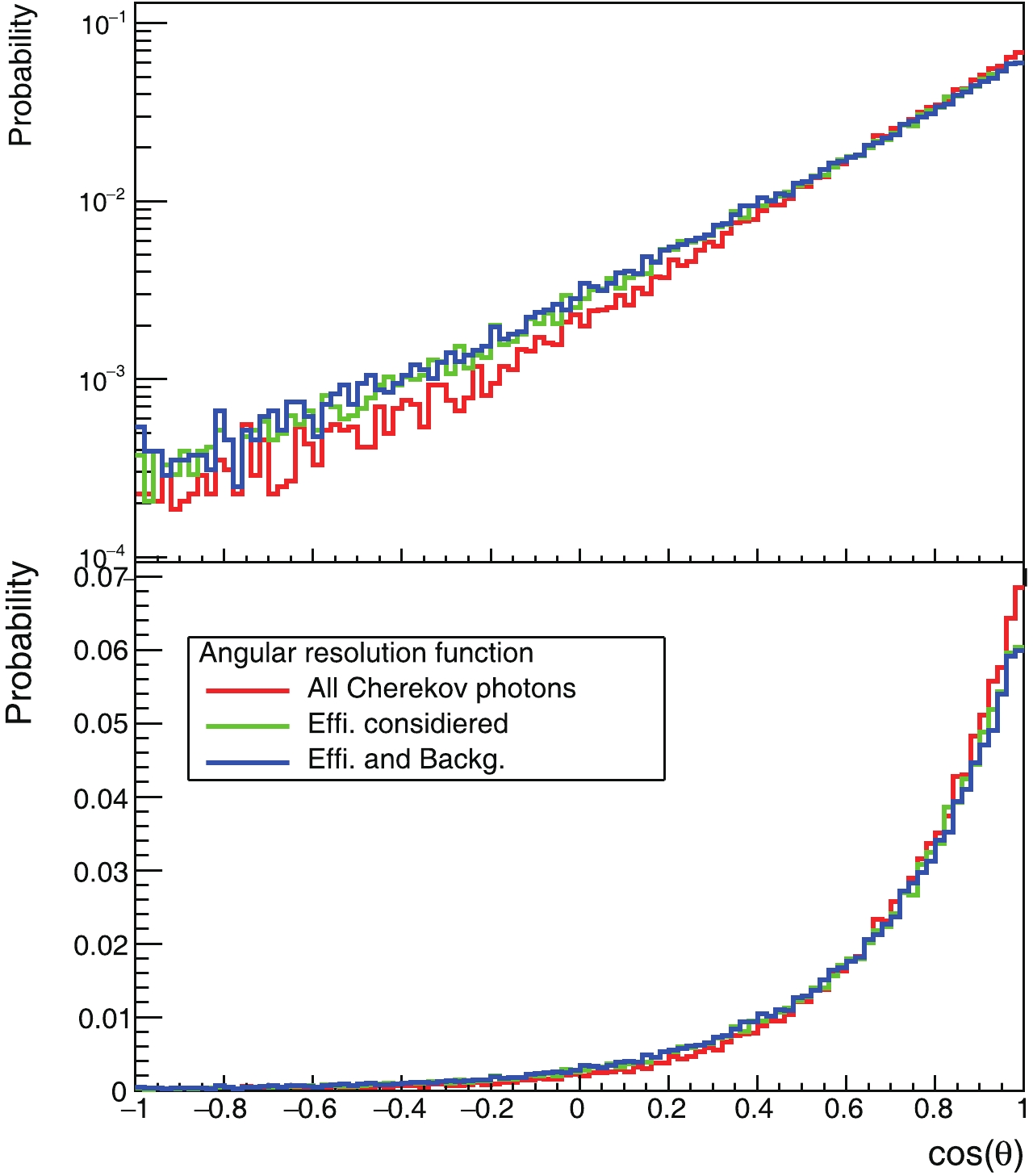
Figure 7. (color online) Angular-response distribution of reconstructed directions relative to electrons’ initial direction, where the electron kinetic energy is in range [0.5, 2] MeV. Upper and lower panels are the same, but the upper panel is plotted on a logarithmic scale to clearly show the non-negligible negative component.
The angular response as a function of energy is shown in Fig. 8 for Case (3). The resolution improves gradually with increasing energy.
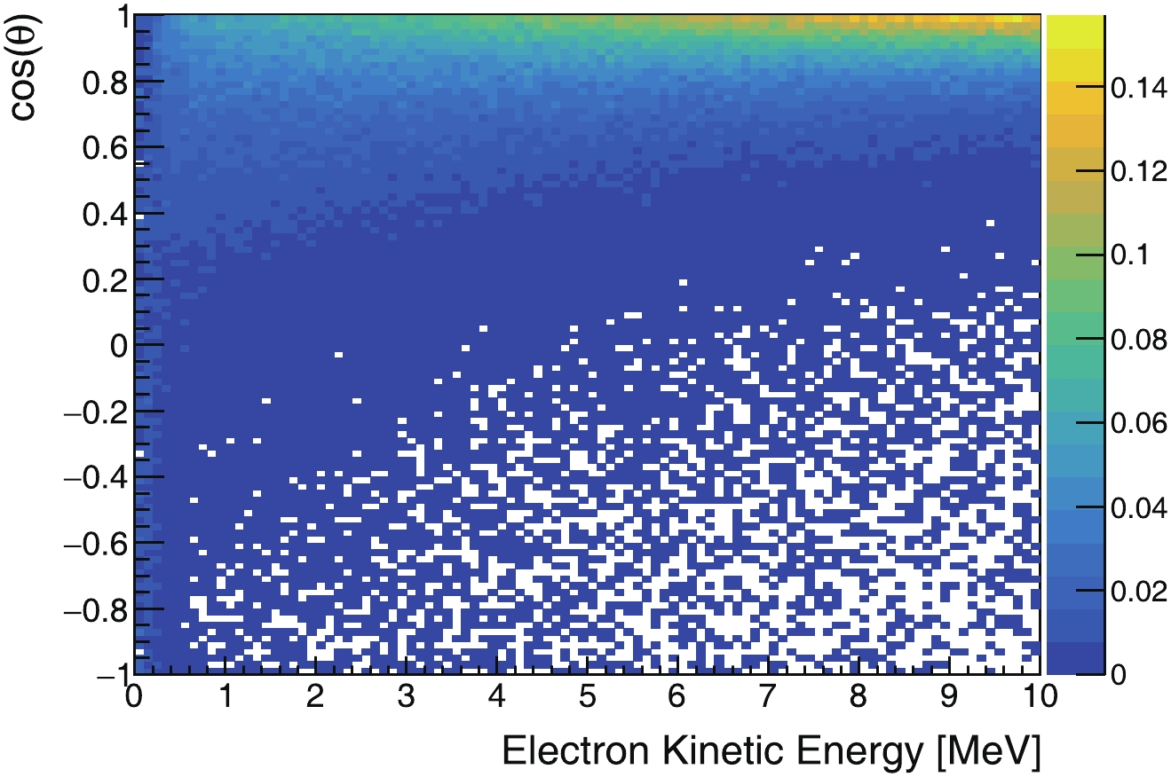
Figure 8. (color online) Angular response versus energy. Projection on cos(θ) for [0.5, 2] MeV electrons is shown in Fig. 7.
-
To extract the geoneutrino signals, we first determine an energy cut and a
$ \cos\theta_{\odot} $ cut, followed by a statistical subtraction to remove the solar-neutrino background. -
The event rate ratio of geo- to solar neutrinos as a function of energy is shown in Fig. 9, according to which we define three observation windows. One is the energy range [0.7, 2.3] MeV, where all
$ ^{\rm{40}} {\rm{K}}$ ,$ ^{\rm{232}} {\rm{Th}}$ , and$ ^{\rm{238}} {\rm{U}}$ geoneutrinos provide contributions. The second is the range [0.7, 1.1] MeV, which is dominated by$ ^{\rm{40}} {\rm{K}}$ neutrinos, and the third is the range [1.1, 2.3] MeV, which is populated by$ ^{\rm{232}} {\rm{Th}}$ and$ ^{\rm{238}} {\rm{U}}$ neutrinos. For events below 0.7 MeV, like the$ \nu_e $ component from$ ^{\rm{40}} {\rm{K}}$ decay, the directional reconstruction is rather poor, hence these events are not usable. For all three observation windows, the solar-neutrino background needs to be suppressed by a factor of 100-200 to enable us to extract geoneutrino signals. In the [0.7, 1.1] MeV window, the dominant solar-neutrino backgrounds are the$ pep $ ,$ ^{13} {\rm{N}}$ , and$ ^{15} {\rm{O}}$ neutrinos, while the$ ^{15} {\rm{O}}$ and$ ^{8} {\rm{B}}$ neutrinos are in the [1.1, 2.3] MeV window.
Figure 9. (color online) Signal-to-background ratio (geo-to-solar-neutrino ratio) as a function of electron kinetic energy.
Followingly, we determine the
$ \cos\theta_{\odot} $ cut. After applying the detected-energy cut of [0.7, 2.3] MeV, the$ \cos\theta_{\odot} $ of the remaining solar- and geo- neutrinos are both plotted in Fig. 10. With a cut at$ \cos\theta_{\odot}<-0.75 $ , the solar neutrinos are suppressed by a factor of 150, and the signal (geo) to background (solar) ratio is about 0.1, closer to unity than the other region.
Figure 10. (color online) The
$ \cos\theta_{\odot}$ distributions of simulated solar and geo- neutrinos, where total statistics are for a 3-kt detector and a 20-year observation period. A detected energy cut at [0.7, 2.3] MeV is applied. -
Using the data sample from our imagined experiment, the number of geoneutrino signals,
$ N_{\rm geo} $ , can be calculated by subtracting the solar-neutrino background:$ N_{\rm geo} = N_{\rm can}-N_{\rm bkg}\times \epsilon, $

(3) where
$ N_{\rm can} $ is the number of all candidates,$ N_{\rm bkg} $ is the background flux, e.g., the solar neutrinos, and$ \epsilon $ is the detection efficiency, including the energy-window cut and the$ \cos\theta_{\odot} $ cut.The uncertainty
$ \sigma_{\rm geo} $ in the geoneutrino counts is$ \sigma_{\rm geo} = \sqrt{\sigma_{\rm candidate}^2 + N_{\rm solar}^2\sigma_{\epsilon}^2 + \epsilon^2\sigma_{\rm solar}^2}, $

(4) where
$ \sigma_{\rm candidate} $ is the statistical uncertainty of the data sample,$ \sigma_{\rm solar} $ is the solar-neutrino-flux uncertainty, and$ \sigma_{\epsilon} $ is the uncertainty in the efficiency.For the solar-neutrino background, pep and B8 neutrinos are dominant. We expect that several proposed experimental approaches, like Jinping [32], LENA [33], THEIA [17], and [34], will improve their uncertainty to a 1% precision. Calibration sources can be deployed to multiple locations of the detector [35]. The calibration source can be a beta source enclosed in a small metal box with a small pinhole as a collimator. With sufficient statistics, a 1% precision is expected.
From our experience, we assume that the detection-efficiency uncertainty, including the energy and the
$ \cos\theta_{\odot} $ cuts, can also reach 1%.For the
$ ^{\rm{40}} {\rm{K}}$ energy window, we further need to subtract the$ ^{\rm{238}} {\rm{U}}$ and$ ^{\rm{232}} {\rm{Th}}$ geoneutrino components as backgrounds. With the advantage of a low reactor-neutrino background, the Jinping Neutrino Experiment can measure the total flux of these neutrinos to better than 5%. -
From the discussion above and the results obtained for angular resolution and expected systematic uncertainties, we can now estimate the precision of the geoneutrino-flux measurement as a function of exposure. We express the sensitivity as
$ {\rm sensitivity} = N_{\rm geo}/\sigma_{\rm geo}, $

(5) which provides the relative precision or the deviation from the null assumption. The study is performed for each of the three energy windows defined in Section 1.4.1 above: one for all geoneutrinos, [0.7, 2.3] MeV, another for the
$ ^{\rm{40}} {\rm{K}}$ geoneutrinos, [0.7, 1.1] MeV, and the third for the$ ^{\rm{238}} {\rm{U}}$ and$ ^{\rm{232}} {\rm{Th}}$ components, [1.1, 2.3] MeV. The results are shown in Fig. 11, Fig. 12, and Fig. 13, respectively.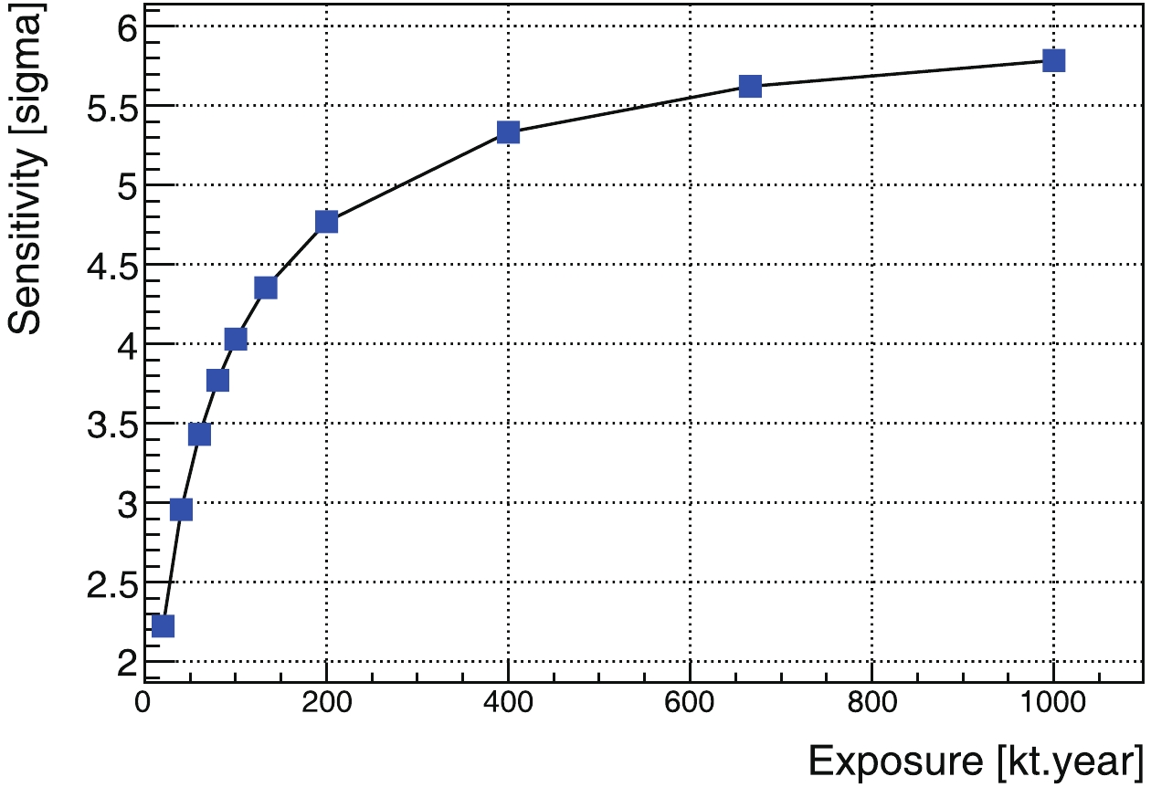
Figure 11. (color online) Discovery sensitivity for all geoneutrinos as a function of exposure.
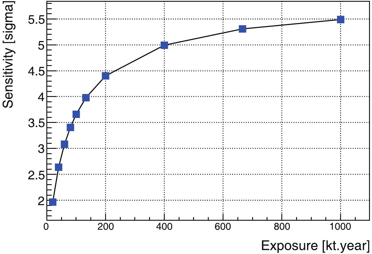
Figure 12. (color online) Discovery sensitivity for 40K geoneutrinos as a function of exposure.

Figure 13. (color online) Discovery sensitivity for 238U and 232Th genoneutrinos as a function of exposure.
Among these results, the most attractive is the one for the
$ ^{\rm{40}} {\rm{K}}$ geoneutrinos, Fig. 12. With a three-kiloton target mass and 20-year data-acquisition time, a 3-σ observation is possible. With a 20-kiloton detector, a 5-σ observation is expected.For the
$ ^{\rm{232}} {\rm{Th}}$ and$ ^{\rm{238}} {\rm{U}}$ region, even with the better signal-to-background ratio shown in Fig. 9, the result is still limited by low statistics. Hence, the expectation is worse than for the$ ^{\rm{40}} {\rm{K}}$ geoneutrinos. -
The key aspects of this study are highlighted below, and their important properties are discussed. We generated solar and geoneutrinos according to models, and propagated the neutrinos to a detector at the Earth's equator, taking into account neutrino oscillations. Neutrino-electron elastic scattering is simulated using standard theoretical formulas. The transport of the recoil electrons and the production of Cherenkov and scintillation photons are all handled by Geant4, using the customized light yield and rise and decay time constants of LAB. Photoelectron detection is sampled according to a 20% detection efficiency for a certain wavelength range. The number of photoelectrons in each event is scaled to reconstruct the recoiling electron's kinetic energy. A weighted-center method is applied to reconstruct the electron directions. With the reconstructed energy and directional distributions, we determined the cuts required to extract geoneutrinos and remove most of the solar neutrino background. The remaining solar-neutrino background is subtracted statistically from the final sample. We scanned the exposure to determine whether it is possible to discover geoneutrinos using this technique. We elaborate on some features of this study below.
-
The directional reconstruction of the recoil electrons is crucial for the overall performance of this detection scheme. The angular resolution governs the final signal-to-background ratio. We find that the scattering of the electrons in the LAB has a primary effect on the resolution. Reconstruction with a limited number of Cherenkov photoelectrons is only the secondary factor, as presented. The density of the LAB is
$ 0.87\times10^3 $ $ {\rm{kg/m}}^3 $ . A further simulation study shows that the angular resolution exhibits no significant improvement unless the density is close to the gaseous state. -
In this study, we assumed a 66.7% detection efficiency, considering the PMT photocathode coverage, photon attenuation in the detector, and a 30% quantum efficiency for photons in the range [300, 550] nm. The detection efficiency is the most optimistic assumption in this entire study. The scintillation emission spectrum of the pure LAB peaks at 340 nm [22], which is close to the UV side and may suffer more absorption than expected. The absorption is caused by the intrinsic absorption band of LAB and cannot be resolved by purification. With the addition of wavelength-shifting materials, the peak can be shifted into the visible range. The absorption could be more severe, and some part of the Cherenkov light can be lost. We hope that this investigation will stimulate further relevant slow-liquid-scintillator research, such as the search for a new solvent and a new wavelength shifter.
-
In this study, we included the critical solar-neutrino background; however, other intrinsic or environmental radiative backgrounds should be considered as well. We take the situation of solar neutrino study at the Borexino experiment as an example [36, 37] to explain our expectations. The radioactive
$ ^{10}\rm{C} $ and$ ^{11}\rm{C} $ background is induced by cosmic-ray muons. At a deeper site, like the Jinping underground laboratory [32], these backgrounds will be suppressed by a factor of 100 or more and become negligible. External photons affect the signal extraction, for example from$ ^{208}\rm{Tl} $ , which can be avoided by a tighter fiducial volume cut. For the internal background, the decay products of U and Th with secular equilibrium are not significant. One aspect worth noting is the$ ^{210}\rm{Bi} $ background. After a few rounds of liquid scintillator purification with distillation, gas and water stripping, and long term monitoring, the remaining$ ^{210}\rm{Bi} $ seems to originate from radon gas absorption on the inner surface of the detector and leaches out by radon's daughter nuclei$ ^{210}\rm{Pb} $ . Good progress has been made by suppressing the thermal convection of the liquid scintillator [38, 39]. Surface cleaning was also mentioned to suppress initial radon contamination. These effects should be considered in the future when developing a more realistic experimental design.Reactor-neutrino backgrounds can be avoided by selecting an experimental site far away from commercial reactors, like the Jinping underground laboratory [32, 40, 41]. Reactor-neutrino fluxes can be efficiently constrained to perform better than 6% [35, 42–44]. The reactor-neutrino background can also be measured in-situ, hence this is not a critical issue.
-
Knowledge of mantle neutrinos is likewise necessary. However, it is only about 30% of the total geoneutrino flux if the detector is placed on a continental site, while the rest originates from the crust. Given the current sensitivity in measuring the total flux and the current angular resolution, we did not pursue this issue further.
-
The K element is volatile, and its concentration in the Earth is not in balance with the refractory U and Th elements. Measurements on the K element in the Earth are of interest to understand the Earth's chemical evolution. The detection of
$ ^{\rm{40}} {\rm{K}}$ neutrinos may lead to new knowledge of the Earth. Previously, only U and Th geoneutrinos could be detected using the inverse beta process with a 1.8 MeV threshold.$ ^{\rm{40}} {\rm{K}}$ geoneutrinos are hard to discover due to their low energy and high solar neutrino background. In this study, we found that liquid scintillator Cherenkov neutrino detectors can be used to detect the$ ^{\rm{40}} {\rm{K}}$ geoneutrinos. Liquid scintillator Cherenkov detectors feature both energy and direction measurements for charged particles. With the elastic scattering process of neutrinos with electrons,$ ^{\rm{40}} {\rm{K}}$ geoneutrinos can be detected without any intrinsic physical threshold. With the directionality, the dominant intrinsic background originating from solar neutrinos in common liquid scintillator detectors can be suppressed. With the studies of MeV electrons in the Geant4 simulation, quantum and detection efficiency, and Cherenkov direction reconstruction, we can detect$ ^{\rm{40}} {\rm{K}}$ energy geoneutrinos with three-standard-deviation accuracy with a kilo-ton scale detector. In this study, the setting of parameters is optimistic; however, we found that this technology is worth further development. -
We used the Standard Solar Model to provide energy sampling of solar neutrinos. Ref. [45] provides the neutrino-energy spectra of all solar neutrinos. We used the neutrino-flux predictions on Earth with the high-metallicity assumption from Ref. [46] as normalization. The characteristic energies and fluxes are summarized in Table A1, and the neutrino energy spectra are shown in Fig. B1.
${{E} }_{\rm{Max} }$ or

${{E} }_{\rm{Line} }$ /MeV

Flux/( $\times10^{10}$ 

${\rm{s}}^{-1}$ 

${\rm{cm}}^{-2}$ )

$pp$ 

0.42 $5.98(1\pm0.006)$ 

$^7{\rm{Be}}$ 

0.38 $0.053(1\pm0.07)$ 

0.86 $0.447(1\pm0.07)$ 

$pep$ 

1.45 $0.0144(1\pm0.012)$ 

$^{13}{\rm{N}}$ 

1.19 $0.0296(1\pm0.14)$ 

$^{15}{\rm{O}}$ 

1.73 $0.0223(1\pm0.15)$ 

$^{17}{\rm{F}}$ 

1.74 $5.52\times10^{-4}(1\pm0.17)$ 

$^8{\rm{B}}$ 

15.8 $5.58\times10^{-4}(1\pm0.14)$ 

$hep$ 

18.5 $8.04\times10^{-7}(1\pm0.30)$ 

Table A1. Characteristic energies and total fluxes of solar neutrinos.
${E}_{\rm{Max}}$ depicts maximum energy for continuous spectra, and${E}_{\rm{Line}}$ depicts discrete lines.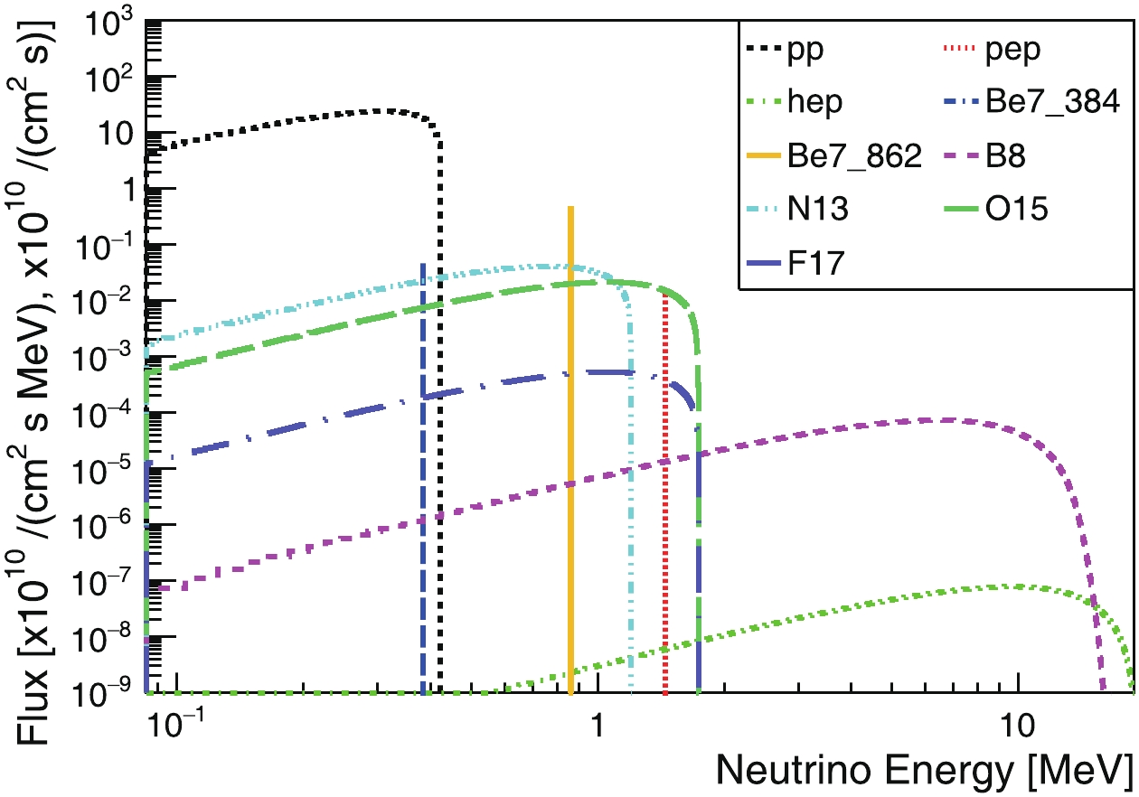
Figure B1. (color online) Predicted non-oscillating solar electron-neutrino energy spectra on Earth, where the unit for continuous spectra is 1010/(cm2 s MeV), and for discrete lines is 1010/(cm2 s).
Solar neutrinos are generated as pure electron neutrinos. Taking into account the oscillation between different neutrino flavors during transit
$\rm{is} $ the Sun [47, 48], the survival probability of electron neutrinos is [49, 50]:$\tag{A1} P^{\odot}_{ee} = \cos^4\theta_{13}\left(\frac{1}{2}+\frac{1}{2}\cos2\theta^M_{12}\cos2\theta_{12}\right), $

where
$ \sin^2\theta_{12} $ = 0.307,$ \sin^2\theta_{13} $ = 0.0241, and$ \theta^M_{12} $ is the revised matter oscillation angle [47–50], which is neutrino energy and electron number density dependent [51].The appearance probability of
$ \nu_{\mu} $ or$ \nu_{\tau} $ is$\tag{A2} P^{\odot}_{e\mu(\tau)} = 1-P^{\odot}_{ee}. $

The probability
$ P^{\odot}_{ee} $ ranges from 0.3 to 0.6. We did not consider neutrino oscillations in the Earth, because the change in probability is less than 5%, which is insignificant for our study. -
There are three dominant heat-producing isotopes in the Earth:
$ ^{\rm{238}} {\rm{U}}$ ,$ ^{\rm{232}} {\rm{Th}}$ , and$ ^{\rm{40}} {\rm{K}}$ . Neutrinos are produced in their decay chains or direct decays:$\tag{B1} \begin{align} ^{238}\rm{U} \rightarrow ^{206}\rm{Pb} + 8\alpha + 6e^- + 6\bar\nu_e + 51.698\; MeV, \end{align} $

$\tag{B2} \begin{align} ^{232}\rm{Th} \rightarrow ^{207}\rm{Pb} + 7\alpha + 4e^- + 4\bar\nu_e + 46.402\; MeV, \end{align} $

$\tag{B3} ^{40}\rm{K} \rightarrow ^{40}\rm{Ca} + e^- + 4\bar\nu_e + 1.311\; MeV\; (89.3\%), $

$\tag{B4} ^{40}\rm{K} + e^- \rightarrow ^{40}\rm{Ar} + \nu_e + 1.505\; MeV\; (10.7\%). $

Electron-antineutrinos are dominant, however 10.7% of the
$ ^{\rm{40}} {\rm{K}}$ decays occur through electron capture, producing electron-neutrinos with an energy of 0.043 MeV. This decay branch is ignored, because it is hard to distinguish using the method proposed in this study. The characteristic energies of these neutrinos are listed in Table B1, and their energy spectra are shown in Fig. B2.Isotope ${E}_{\rm Max}$ /MeV

Flux/( $\times10^{10}$ 

${\rm{s}}^{-1}$ 

${\rm{cm}}^{-2}$ )

Crust 40K 1.31 0.00160 232Th 2.26 0.00043 238U 3.27 0.00047 Mantle 40K 1.31 0.00057 232Th 2.26 0.00005 238U 3.27 0.00008 Table B1. Characteristic energies and total fluxes of geoneutrinos. EMax depicts maximum energy for continuous spectra.
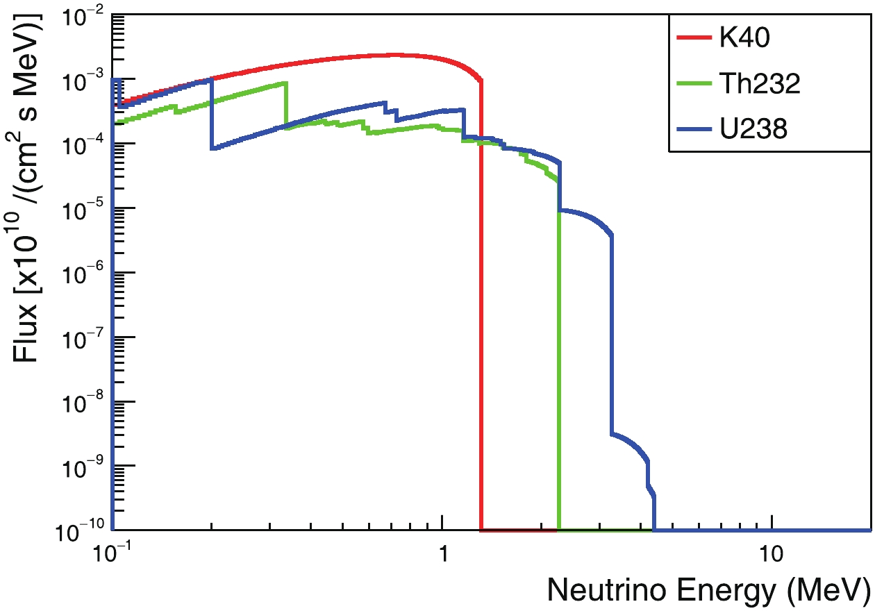
Figure B2. (color online) Predicted non-oscillating geo electron-antineutrino energy spectra on the Earth's surface.
We used a layered Earth model to simulate the geoneutrinos. In this model, the Earth is assumed to consist of three layers: the core, mantle, and crust. We assume that the mantle and crustal layers have uniform distributions of
$ ^{40} {\rm{K}}$ ,$ ^{232} {\rm{Th}}$ and$ ^{238} {\rm{U}}$ , and that there is no radioactivity from the core.The entire volume of the Earth is divided into many small cells, each of which has a coordinate
$ \vec{r} $ . Electron antineutrinos are sampled from each cell. The differential flux of electron antineutrinos from each cell to the surface neutrino detector at$ \vec{d} $ can be written as [40, 41]:$\tag{B5} {\rm d}\phi(\vec{r})_{e} = \frac{X \lambda N_A}{\mu} n_{\nu} P_{ee}^\oplus \frac{A(\vec r) \rho(\vec{r})}{4\pi |\vec{r}-\vec{d}|^2}{\rm d}v, $

where X is the natural isotopic mole fraction of each isotope, λ is the corresponding decay constant,
$ N_A $ is the Avogadro's number, µ is the atomic mole mass,$ n_{\nu} $ is the number of neutrinos per decay,$ P_{ee}^\oplus $ is the average survival probability,$ A(\vec r) $ is the abundance of each element in kg/kg,$ \rho(\vec r) $ is the local density at each location, and$ |\vec{r}-\vec{d}| $ provides the distance from each cell$ \vec{r} $ to our detector at$ \vec{d} $ .We take the outer radii of the core, mantle and crust to be 3480, 6321, and 6371 km [52], respectively, with their corresponding densities at 11.3, 5.0, and 3.0 g/cm3. The element abundances of K, Th, and U are set to match the integrated flux predictions, as in Refs. [40, 41], and the values are given in Table B2. This simplified layered model is not as sophisticated as that provided in Ref. [53]; however, it is nevertheless sufficient for our demonstration purposes. The rest of the parameters are taken from Ref. [41]. The total fluxes of the predicted geoneutrinos are summarized in Table B1. The non-oscillating neutrino spectra of
$ ^{40} {\rm{K}}$ ,$ ^{232} {\rm{Th}}$ , and$ ^{238} {\rm{U}}$ at the detection site are shown in Fig. B2.K [kg/kg] Th [kg/kg] U [kg/kg] Crust 1.16 × 10⁻² 5.25 × 10⁻⁶ 1.35 × 10⁻⁶ Mantle 152 × 10−6 21.9 × 10⁻⁹ 8.0 × 10⁻⁹ Table B2. Element abundance of K, Th and U in the mantle and crust used for this study.
The geoneutrino oscillation probability varies only by about 2% within the energy range [0, 3.5] MeV [40], hence it is treated as a constant, i.e.,
$ P_{ee}^\oplus = 0.553 $ . The appearance probability of the$ \nu_{\mu} $ or$ \nu_{\tau} $ components is$ \tag{B6} P^{\oplus}_{e\mu(\tau)} = 1-P^{\oplus}_{ee}. $

-
The differential scattering cross-sections for neutrinos of energy
$ E_{\nu} $ and recoil electrons with kinetic energy$ T_e $ can be written, e.g. in Ref. [54], as:$\tag{C1} \frac{{\rm d}\sigma(E_{\nu},T_e)}{{\rm d}T_e} = \frac{\sigma_0}{m_e}\left[g_1^2+g_2^2\left(1-\frac{T_e}{E_{\nu}}\right)^2-g_1g_2\frac{m_eT_e}{E_{\nu}^2}\right], $

where
$ m_e $ represents the electron mass. For$ \nu_e $ and$ \bar\nu_e $ ,$ g_1 $ and$ g_2 $ are:$ \tag{C2} \begin{split} g_1^{(\nu_e)} =& g_2^{(\bar\nu_e)} = \frac{1}{2}+\sin^2\theta_W\simeq0.73,\\ g_2^{(\nu_e)} =& g_1^{(\bar\nu_e)} = \sin^2\theta_W\simeq0.23, \end{split} $

where
$ \theta_W $ depicts the Weinberg angle, and for$ \nu_{\mu,\tau} $ ,$ g_1 $ and$ g_2 $ are:$ \tag{C3} \begin{split} g_1^{(\nu_{\mu,\tau})} =& g_2^{(\bar\nu_{\mu,\tau})} = -\frac{1}{2}+\sin^2\theta_W\simeq-0.27,\\ g_2^{(\nu_{\mu,\tau})} =& g_1^{(\bar\nu_{\mu,\tau})} = \sin^2\theta_W\simeq0.23. \end{split} $

The constant
$ \sigma_0 $ is$ \tag{C4} \sigma_0 = \frac{2G_F^2m_e^2}{\pi}\simeq88.06\times10^{-46}\ \rm{cm}^2. $

The differential cross-section is shown in Fig. C1. The antineutrino cross-section is lower than that of the neutrinos by several factors, and the recoil electrons produced by
$ \bar\nu_e $ tend to have lower kinetic energies.
Figure C1. (color online) Neutrino-electron-scattering differential cross-section for
$ \nu_e, \nu_{\mu,\tau}, \bar\nu_e$ , and$ \bar\nu_{\mu,\tau}$ at neutrino energies 1 and 2 MeV.With the above formulas, the distribution of the recoiling electrons' kinetic energy is calculated:
$\tag{C5} \frac{{\rm d}N}{{\rm d}T} = N_e\int \left [ \sum\limits_{\nu} \frac{{\rm d}\sigma(E_{\nu},T_e)}{{\rm d}T_e} P_{e\nu}\right ] F(E_{\nu}){\rm d}E_{\nu}, $

where
$ \frac{{\rm d}N}{{\rm d}T} $ is the number of scattered electrons N per unit electron kinetic energy T, and$ N_e $ is the number of target electrons. The integral spans all neutrino energies$ E_{\nu} $ , and the sum spans all neutrino flavors$ \nu $ , which are$ \nu_e $ ,$ \nu_{\mu} $ $ \nu_{\tau} $ ,$ \bar\nu_e $ ,$ \bar\nu_{\mu} $ , and$ \bar\nu_{\tau} $ .$ \frac{{\rm d}\sigma(E_{\nu},T_e)}{{\rm d}T_e} $ is given by Eq. (C1),$ P_{e\nu} $ is the oscillation probability, and$ F(E_{\nu}) $ is the flux of neutrinos.With the condition of energy and momentum conservation, the cosine of the scattering angle between the initial neutrino direction and the scattered-electron direction can be determined from:
$ \tag{C6} \cos\theta = \frac{1+m_e/E_{\nu}}{\sqrt{1+2m_e/T_e}}. $

The resulting
$ \cos\theta $ distribution is shown in Fig. C2. Notably, although the directional correlation between the incoming neutrino and the recoil electron is weak at low energies, for example, at 1 MeV, with a cut of the kinetic energy of the recoil electron, the correlation still exists and can be employed. This feature is also shown in Fig. C2.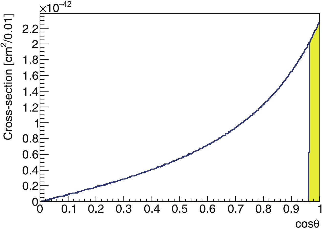
Figure C2. (color online) Cosine distribution of scattering angle between initial neutrino direction and recoiling electron. In this plot, we use 1 MeV
$ \nu_e$ as an example. Shaded area shows result with a cut on the electron kinetic energy at 0.7 MeV.After considering neutrino oscillation and neutrino-electron scattering, the kinetic energy spectrum of recoiling electrons of solar- and geo-neutrinos are shown in Fig. C3, and Fig. C4, respectively.
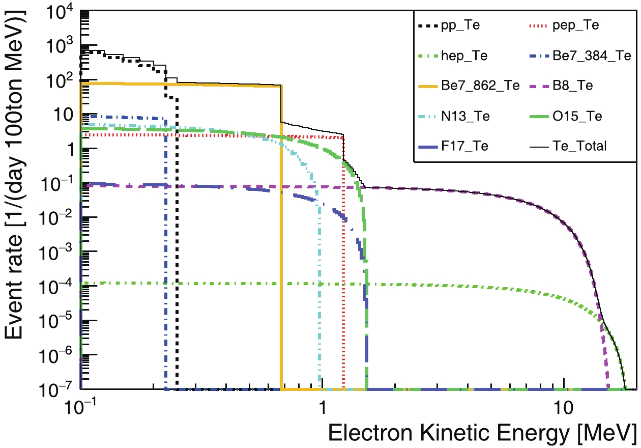
Figure C3. (color online) Recoiling-electron kinetic-energy spectra from solar neutrinos.

Figure C4. (color online) Recoiling-electron kinetic-energy spectra from geo neutrinos.


 DownLoad: