-
Recently, the Event Horizon Telescope (EHT) Collaboration presented images of black holes at the center of the Messier
$ 87^{*} $ (${\rm{M}} 87^{*} $ ) galaxy and the Milky Way [1−5]. These images observed by the EHT are an important validation of general relativity (GR) and share a common feature that always presented as a black disk surrounded by a bright ring. Owing to the strong gravity of a black hole, photons may travel around it many times and then escape to the screen of the observer, leading to a bright ring. The black disk represents the region in which the photons are fully absorbed by the black hole, which is known as the black hole shadow.The shadows of different types of black holes have been theoretically investigated in recent years. Synge was the first to discover that the shadow contour of a black hole is a standard circle [6]. For a rotating black hole, the shadow deforms in the direction of rotation and has a D-shape [7, 8]. Considering that there is always a significant amount of accretion matter around black holes in the universe, the spectrum of the accretion disk around a Kerr black hole was investigated but not plotted [9]. Subsequently, the image of the accretion disk was obtained from a physical model of the thin gas disk surrounding a Schwarzschild black hole, and the appearance of the shadow and photon ring was found to be related to accretion radiation [10]. Although the intensity depends on the details of accretion flow, its outline is only determined by the spacetime itself and corresponds to the apparent shape of photon orbits captured by the observer. By considering spherically symmetric accretion, the shadow of a Schwarzschild black hole has also been explored [11]. Based on the optical and geometrically thin disk around a Schwarzschild black hole, Gralla et al. made the groundbreaking discovery that black holes not only have photon and lensing rings, but also direct emission [12]. Since then, many related studies on different accretion models have been continuously conducted [13−36].
Interestingly, a thin-shell wormhole (TSW), another special object in our universe, is a topological structure that connects two spacetimes through a throat, which was originally indicated by Misner and Wheeler [37]. Morris and Thorne were the first to propose the concept of a traversable wormhole and showed that exotic matter can be present in its throat [38]. A wormhole produced by surgically grafting two Schwarzschild spacetimes allows a traveler to avoid regions of exotic matter while traveling through the wormhole without experiencing any forces, tides, or other disturbances [39, 40]. These types of wormholes are simple and allow for the minimization of violations of the null energy condition while enabling partial dynamical stability analysis and further constraints on the equation of state of exotic matter. Exploring the stability of wormhole models is important in determining whether a wormhole is traversable. In Ref. [41], Poisson and Visser investigated the stability of a TSW under linear perturbations. Subsequent studies extended this work to more general cases [42], and nonlinear situations have also attracted considerable attention [43−46]. More importantly, it is generally believed that the exploration of the light ring and shadow of a wormhole can help further understand the structure of wormholes. The formation of a Schwarzschild TSW shadow is closely related to the position of the light source and observer [47]. For a Reissner-Nordstrom asymmetric thin-shell wormhole (ATSW), Wielgus et al. discovered that the image seen by the observer may contain a photon ring on the observer's side and a photon ring on the other side of the wormhole [48]. In the framework of Palatini f(R) gravity, it is possible to observe double shadows [49]. Considering the ATSW model, the impact parameter of null geodesics in a wormhole is generally discontinuous, and a novel shadow appears in three cases. In one case, the size of the shadow depends on the size of the photon sphere on the other side of the spacetime and is relatively small compared to that of the black hole case [50]. The novel ATSW shadow structure observed when there was an accretion disk in the observer's spacetime was previously explored, which was found to be noticeably different from that in the black hole case [51].
The problem with GR is that there is a singularity in the spacetime where the curvature becomes infinite. Quantum gravity theory may be regarded as a perfect candidate to circumvent this problem. At present, a self-consistent quantum gravity theory is lacking. Therefore, many theories that correct gravity or quantum mechanics have emerged to provide extensive insight into quantum gravity. For example, Bonanno and Reuter used the renormalization group method to obtain a class of Schwarzschild black holes renormalized by considering a type of nonlinear transformation group in classical mechanics [52, 53]. These black holes can terminate Hawking's evaporation process before reaching the critical mass, replacing the singularity with a smooth de Sitter core to avoid exposing the singularity, which is consistent with the cosmic censorship hypothesis [53]. In such black holes, there are two parameters, Ω and γ, which originate from non-perturbative renormalization group theory and an identification of distance scale cutoff, respectively [53, 54]. In [53, 54], the curvature at the center of black hole avoids the singularity perfectly owing to the existence of Ω and γ. Thus, it is clear that a renormalization group improved (RGI) black hole can present the effect of quantum gravity via Ω and γ. Using this black hole, we studied the shadow characteristics of an RGI black hole surrounded by spherical accretion models and found the effect of quantum gravity on the shadow appearance [17]. In addition, many other studies related to this black hole have been conducted, as referenced in [54−56]. Using Visser's method, the spacetime with RGI terms can also be cut and pasted as an ATSW, which would exhibit more features of parameters Ω and γ. To further explore the feature of quantum gravity, considering a thin disk on one side of an ATSW, we study the observable appearance of an ATSW encoded with the RGI spacetime on two sides. In particular, when photons are emitted from the thin disk, some with a certain impact parameter approach the throat but do not fall into it. However, some photons fall into the throat and then turn back owing to the asymmetric structure, eventually reaching infinity. Considering this, we carefully study the trajectories of photons and investigate the novel light rings of the RGI-ATSW. Furthermore, the effects of the RGI parameters on the observable appearance of the ATSW are addressed throughout the study.
The structure of this paper is as follows. In Sec. II, the ATSW system with RGI terms is introduced and its geodesics are briefly studied. We investigate the light deflection of wormhole and analyze the photon trajectories in Sec. III, and the transfer function of the ATSW when a thin accretion disk is located on one side of the spacetime, i.e.,
$ M_{1} $ , and obtain its optical appearance using two different radiation scenarios for the disk in Sec. IV. Additionally, we compare the appearance of the RGI-ATSW with those of a Schwarzschild-ATSW and an RGI black hole. Finally, in Sec. V, we present our conclusions. -
Using the well-known cut and paste approach provided by Visser, it is easy to construct an ATSW structure in which the two spacetimes are joined by the throat [39], where the different mass parameters in the two spacetimes reflect the asymmetric structure of the TSW. In [53], the well-known RGI black hole solution was obtained, which can be represented as
$ {\rm d} s^2 = -F (r) {\rm d} t^2+ F(r)^{-1} {\rm d} r^2+r^2 {\rm d} \theta ^2 +r^2 {\sin^2\theta} {\rm d} \varphi^2, $

(1) with
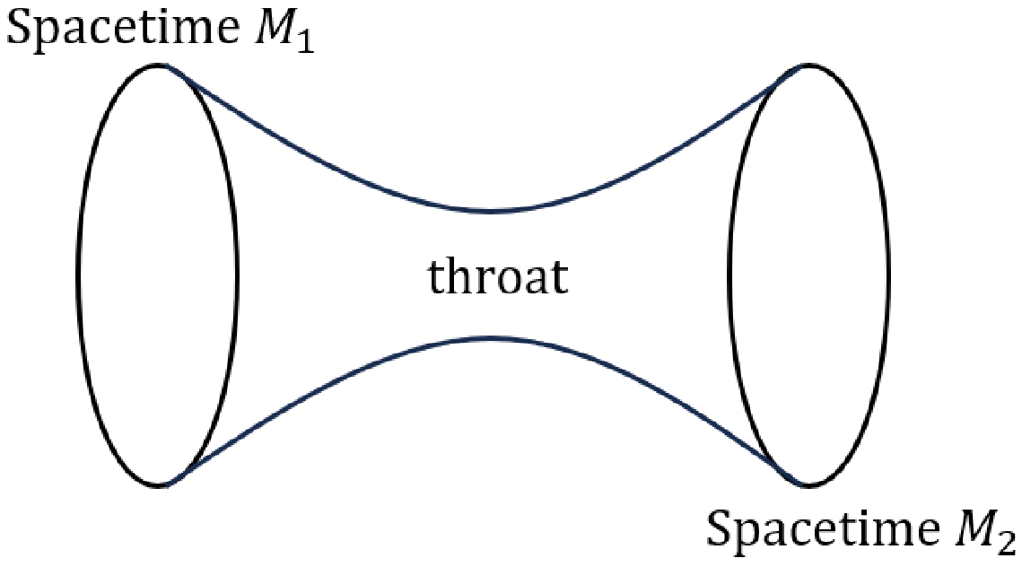
$ F(r) = 1-\dfrac{2M}{r} \left( 1+\dfrac{\Omega M^{2}}{r^{2}}+\dfrac{\gamma \Omega M^{3}}{r^{3}} \right) ^{-1} $ , where M represents the black hole mass, and γ and Ω are dimensionless parameters obtained by distance scale intercept identification and non-perturbative renormalization group theory, respectively [53, 54]. When$ F(r) = 0 $ , there are two roots, representing the inner and outer horizons of the black hole. The outer horizon is commonly referred to as the event horizon, denoted by$ r_+ $ . According to Visser's method, spacetime structure (1) out of the horizon can be used to construct an ATSW. In general, the profile of a wormhole can be viewed as Fig. 1. The two spacetimes with different mass parameters are defined as$ M_{1} $ and$ M_{2} $ , which are joined through a thin-shell to form a new manifold,$ M\equiv M_{1} \cup M_{2} $ . In this case, the spacetimes and throat produce an ATSW with different mass parameters. Therefore, when the two spacetimes out of the throat are regarded as (1), the metric can be rewritten as$ {\rm d} s_{i}^2 = -F_{i} (r_{i}) {\rm d} t_{i}^2+ F_{i}(r_{i})^{-1} {\rm d} r_{i}^2+r_{i}^2 {\rm d} \theta_{i} ^2 +r_{i}^2 {\sin^2\theta_{i}} {\rm d} \varphi_{i}^2, $

(2) where
$ i = 1,2 $ , and$ F_{i}(r_{i}) = 1-\dfrac{2M_{i}}{r_{i}} \left( 1+\dfrac{\Omega M_{i}^{2}}{r_{i}^{2}}+\dfrac{\gamma \Omega M_{i}^{3}}{r_{i}^{3}} \right) ^{-1},\quad r\geq R, $

(3) where R represents the radius of the throat. Here, we consider R to be greater than the event horizon of spacetime (1); hence, it satisfies
$ R> \max\left\{ r_{1_{+}}, r_{2_{+} } \right\} $ . The$ \dot R $ denotes the 4-velocity of the thin-shell. For simplicity, we assume the thin-shell wormhole to be static, i.e.,$ \dot R = 0 $ .First, we focus on the motion of photons in the RGI-ATSW model. For simplicity, we fix the photons on the equatorial plane and assume that there is only a gravitational interaction between photons and the throat and that the 4-momentum of the photons remains constant during the pass through the wormhole. Additionally, we consider continuity of the metric in spacetime M, i.e.,
$ g_{ab}^{M_{1}}(R) = g_{ab}^{M_{2}}(R) $ [50]. The energy E and angular momentum L are conserved along the geodesics:$ E_{i} = -p_{t_{i}}, \quad L_{i} = p_{\varphi_{i}}. $

(4) Therefore, the motion equation of null geodesics can be written as
$ \dfrac{(p_{i}^{r_{i}})^{2}}{F_{i}(r_{i})} = \dfrac{p_{t_{i}}^{2}}{F_{i}(r_{i})}-\dfrac{p_{\varphi_{i}}^{2}}{r_{i}^{2}}, $

(5) where
$ p^{a} $ is the 4-momentum of the massless particles along the geodesic,$p^{a} = \dfrac{{\rm d} x^{\mu}}{{\rm d} \lambda}$ , and λ is an affine parameter. The affine parameter λ can be redefined as$ \lambda = \lambda/E $ , and$ b = |L|/E $ is the impact parameter. Therefore, Eq.(5) can be rewritten as$ (p_{i}^{r_{i}})^{2} = \dfrac{1}{b_{i}^{2}}-\dfrac{F_{i}(r_{i})}{r_{i}^{2}}. $

(6) Here, the effective potential
$V_{\rm eff}(r_{i})$ is introduced,$ V_{\rm eff}(r_{i}) = \dfrac{F_{i}(r_{i})}{r_{i}^{2}}. $

(7) The photon sphere condition requires
$V_{\rm eff}(r_{p}) = \dfrac{1}{b_{c}^{2}}$ and$V'_{\rm eff}(r_{p}) = 0$ , where$ r_{p} $ is the radius of the photon sphere, and$ b_{c} $ represents the corresponding critical impact parameter. The effective potential of the RGI-ATSW is shown in Fig. 2, which is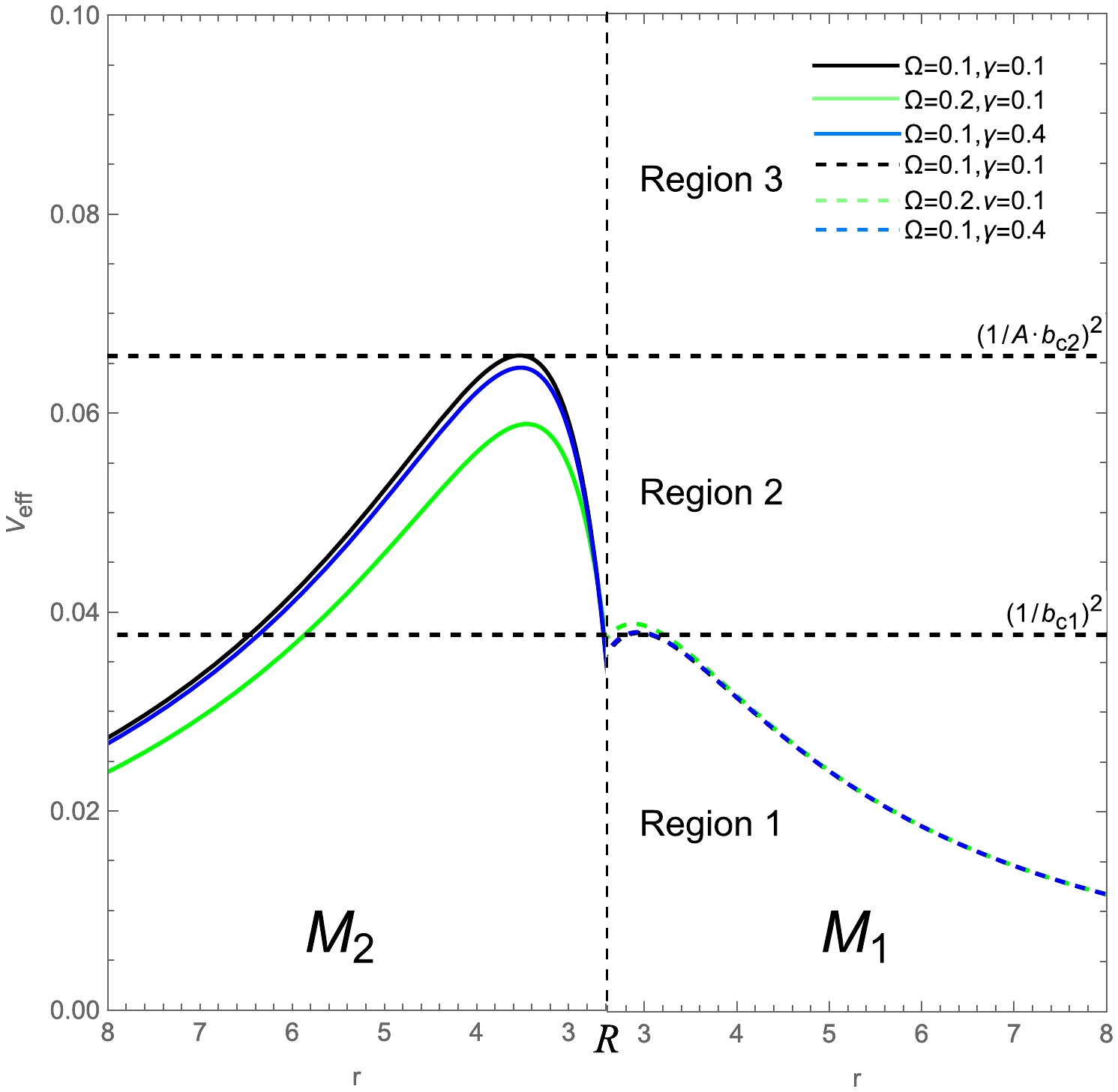
Figure 2. (color online) Effective potential of the RGI-ATSW, where the dashed and solid lines represent spacetimes
$ M_1 $ and$ M_2 $ , and$ M_1 = 1 $ ,$ M_2 = 1.2 $ ,$ R = 2.6 $ . For$ \Omega = 0.1 $ and$ \gamma = 0.1 $ , the impact parameter$ b_{c1} \approx 5.13527 $ and$ A \cdot b_{c2} \approx 3.89905 $ .According to Fig. 2, the effective potentials of the two spacetimes are equal at the throat, and the maximum effective potential in spacetime
$ M_2 $ is greater than that in$ M_1 $ . Taking$ \Omega = 0.1 $ and$ \gamma = 0.1 $ as an example, the effective potentials can be classified into three cases. Case 1 (Region 1): The photon with impact parameter$ b_1>5.13527 $ from$ M_1 $ is reflected by the potential barrier of$ M_1 $ when it is close to the throat and then reaches the infinity of$ M_1 $ . Case 2 (Region 2): The photon with impact parameter$ 3.89905<b_1<5.13527 $ falls into the throat and then reaches the spacetime$ M_2 $ through the throat but is reflected back to$ M_1 $ by the potential barrier of$ M_2 $ , finally reaching infinity in$ M_1 $ . Case 3 (Region 3): The photon with impact parameter$ b_1<3.89905 $ falls into the throat and enters the spacetime$ M_2 $ , and eventually, it no longer returns to$ M_1 $ .Photons with
$ b>b_{c} $ may escape to infinity, resulting in the light ring captured by the observer, whereas photons with$ b<b_{c} $ are completely absorbed by the throat. Photons with$ b = b_{c} $ forever rotate at the location of the photon sphere. The impact parameters$ b_i = |L_i|/E_i $ between two spacetimes can be satisfied by [50]$ \dfrac{b_{1}}{b_{2}} = \sqrt{ \dfrac{F_{2}(R)}{F_{1}(R)}} = \sqrt{\dfrac{1-\dfrac{2M_{2}}{R} \left( 1+\dfrac{\Omega M_{2}^{2}}{R^{2}}+\dfrac{\gamma \Omega M_{2}^{3}}{R^{3}} \right) ^{-1}}{1-\dfrac{2M_{1}}{R} \left( 1+\dfrac{\Omega M_{1}^{2}}{R^{2}}+\dfrac{\gamma \Omega M_{1}^{3}}{R^{3}} \right) ^{-1}}}\equiv A. $

(8) The deflection of light rays in the TSW model differs from that for black holes, and the values of
$ M_{1} $ and$ M_{2} $ are particularly important in the case of wormholes. For the TSW, when$ F_{1}(R) = F_{2}(R) $ and$ M_{1} = M_{2} $ 1 , the two spacetimes are symmetrical. When$ M_{1}\neq M_{2} $ , the spacetimes are no longer symmetrical. In this case, for$ R<r_{p1} $ , note that a photon sphere in spacetime$ M_{1} $ would obscure the event horizon [50]. Therefore, the photon motion in the wormhole is similar to that in a black hole, and it is difficult to distinguish between a wormhole and black hole by direct optical observation. However, for the case of$ M_{1} < M_{2} $ , if light rays in spacetime$ M_{1} $ satisfy$ b_{1} < b_{c1} $ , the photons fall into the throat and reach spacetime$ M_2 $ . Furthermore, owing to$ b_{c1}<b_{c2} $ , if we consider$ b_2 > b_{c2} $ , this implies that$ b_{c1} > b_1 > A \cdot b_{c2} $ . This indicates that the photon would return to spacetime$ M_{1} $ through the throat in this condition. Therefore, these photons are interesting because they contribute to the intensity of the light ring, which may act as a tool for distinguishing a wormhole from a black hole. Moreover, when$ M_{1} > M_{2} $ , it has been claimed that the shadow of the wormhole observed by the observer is the same as in the case of a black hole [50]. Therefore, in this study, we only focus on the case of$ M_{1} < M_{2} $ and$ R<r_{p1} $ and use several accepted choices of parameters to study the observed images of the RGI-ATSW, i.e.,$ M_{1} = 1 $ ,$ M_{2} = 1.2 $ , and$ R = 2.6 $ . -
To investigate the light deflection in the RGI-ATSW, we must first obtain the equation of the light trajectory. Using Eq. (6), we can easily obtain
$\dfrac{{\rm d}r_{i}}{{\rm d}\varphi_{i}} = \pm r_{i}^2 \sqrt{ \dfrac{1}{b_{i}^2}-\dfrac{F_{i}(r_{i})}{r_{i}^2} }$ , where$ \pm $ correspond to the clockwise and counterclockwise deflections of the light ray, respectively. By introducing a new parameter$ x = 1/r $ , we have$\begin{aligned}[b] G_{i}(x_{i}) \equiv\;& \dfrac{{\rm d}x_{i}}{{\rm d}\varphi_{i}} \\=\;& \sqrt{\dfrac{1}{b_{i}^{2}}-x_{i}^{2}\left[ 1-2M_{i}x_{i}\left( 1+\Omega M_{i}^{2}x_{i}^{2}+\gamma \Omega M_{i}^{3}x_{i}^{3}\right) ^{-1}\right] }.\end{aligned} $

(9) Based on this equation, we can obtain the turning points of light rays. To further study the deflection angle, we divide the trajectories into three branches:
$ 1) $ $ b_{1}>b_{c1} $ : In spacetime$ M_{1} $ , the photons emitted from infinity approach the photon sphere. However, this type of photon does not fall into the photon sphere; hence, they return to the infinity of spacetime$ M_{1} $ .$ 2) $ $ A \cdot b_{c2} < b_{1} < b_{c1} $ : The emitted photons in$ M_{1} $ fall into the throat and then reach$ M_{2} $ . However, they return to$ M_{1} $ through the throat and finally reach the infinity of$ M_{1} $ .$ 3) $ $ b_{1}<A \cdot b_{c2} $ : The emitted photons in$ M_{1} $ reach$ M_{2} $ and finally the infinity of$ M_{2} $ .For
$ b_{1}>b_{c1} $ , there is a turning point in spacetime$ M_{1} $ , which exactly corresponds to the smallest positive real root of$ G_{1}(x_{1}) = 0 $ and is denoted as$x_{1_{\min}}$ . Based on Eq. (9), for a trajectory with impact parameter$ b_{1} $ outside the photon sphere, the total change in azimuth φ can be expressed as follows:$ \varphi_{1} (b_{1}) = 2\int_{0}^{x_{1_{\min}}} \dfrac{{\rm d}x_{1}}{\sqrt{G_{1}(x_{1})}}. $

(10) For
$ A \cdot b_{c2} < b_{1} < b_{c1} $ , we divide the change in the azimuth angle into two parts. The change in the azimuth angle from infinity to the throat in spacetime$ M_{1} $ is given by$ \varphi_{1}^* (b_{1}) = \int_{0}^{\frac{1}{R}} \dfrac{{\rm d}x_{1}}{\sqrt{G_{1}(x_{1})}}. $

(11) In this case, the turning point of the light ray trajectory is located in spacetime
$ M_{2} $ , corresponding to the largest positive real root satisfying$ G_{2}(x_{2}) = 0 $ , denoted by$ x_{2_{max}} $ . Thus, the change in the azimuth angle in$ M_{2} $ is given by$ \varphi_{2} (b_{2}) = 2\int_{x_{2_{\max}}}^{\frac{1}{R}} \dfrac{{\rm d}x_{2}}{\sqrt{G_{2}(x_{2})}}. $

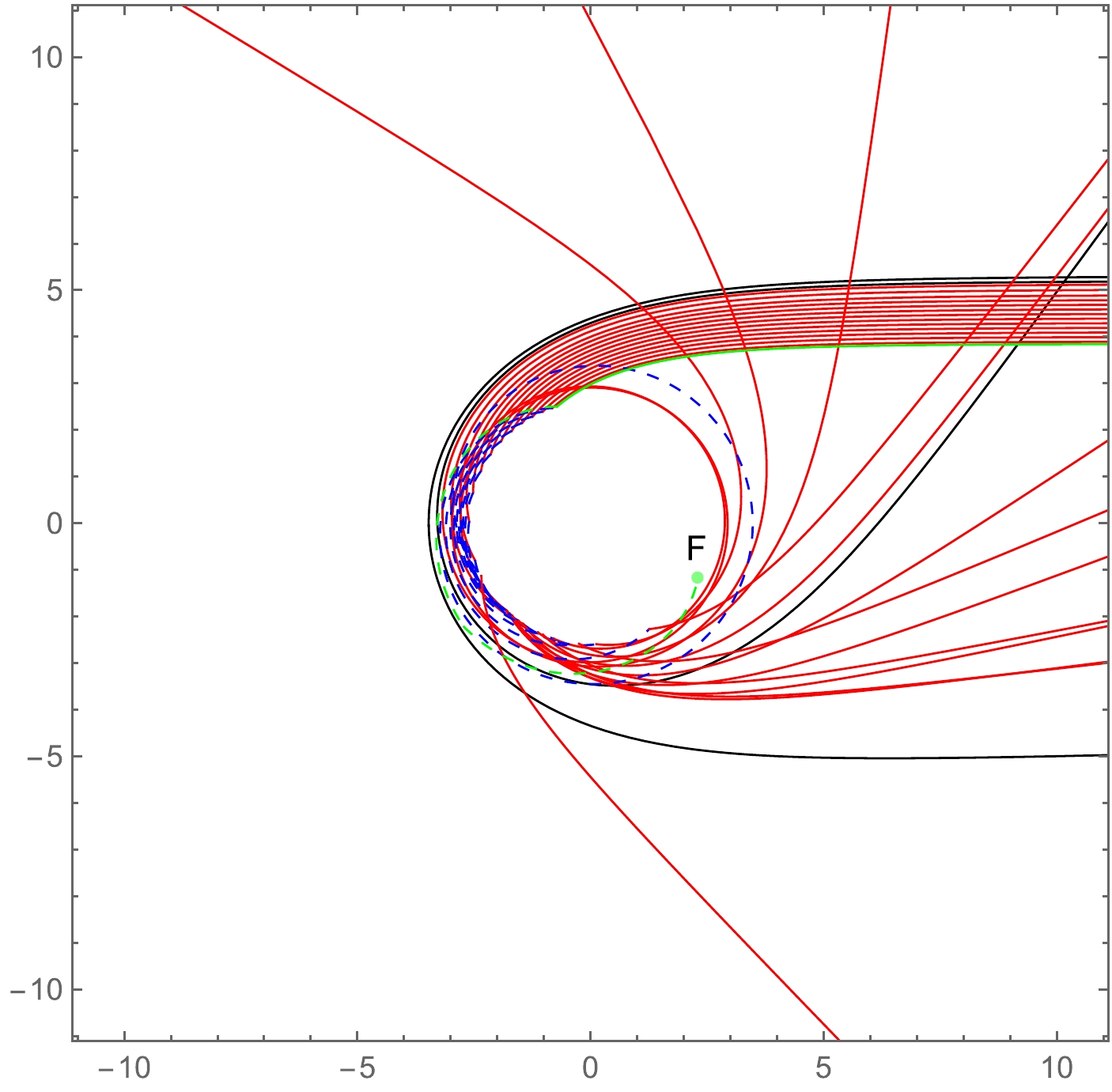
(12) Using Eqs. (9)−(12), we select several values for Ω and γ and show the light ray trajectories of the RGI-ATSW in polar coordinates (r, φ) in Fig. 3. The light rays originate from the North Pole, i.e., on the right side of the figures. Figure 4 shows a set of possible photon trajectories when
$ \Omega = 0.1 $ and$ \gamma = 0.1 $ .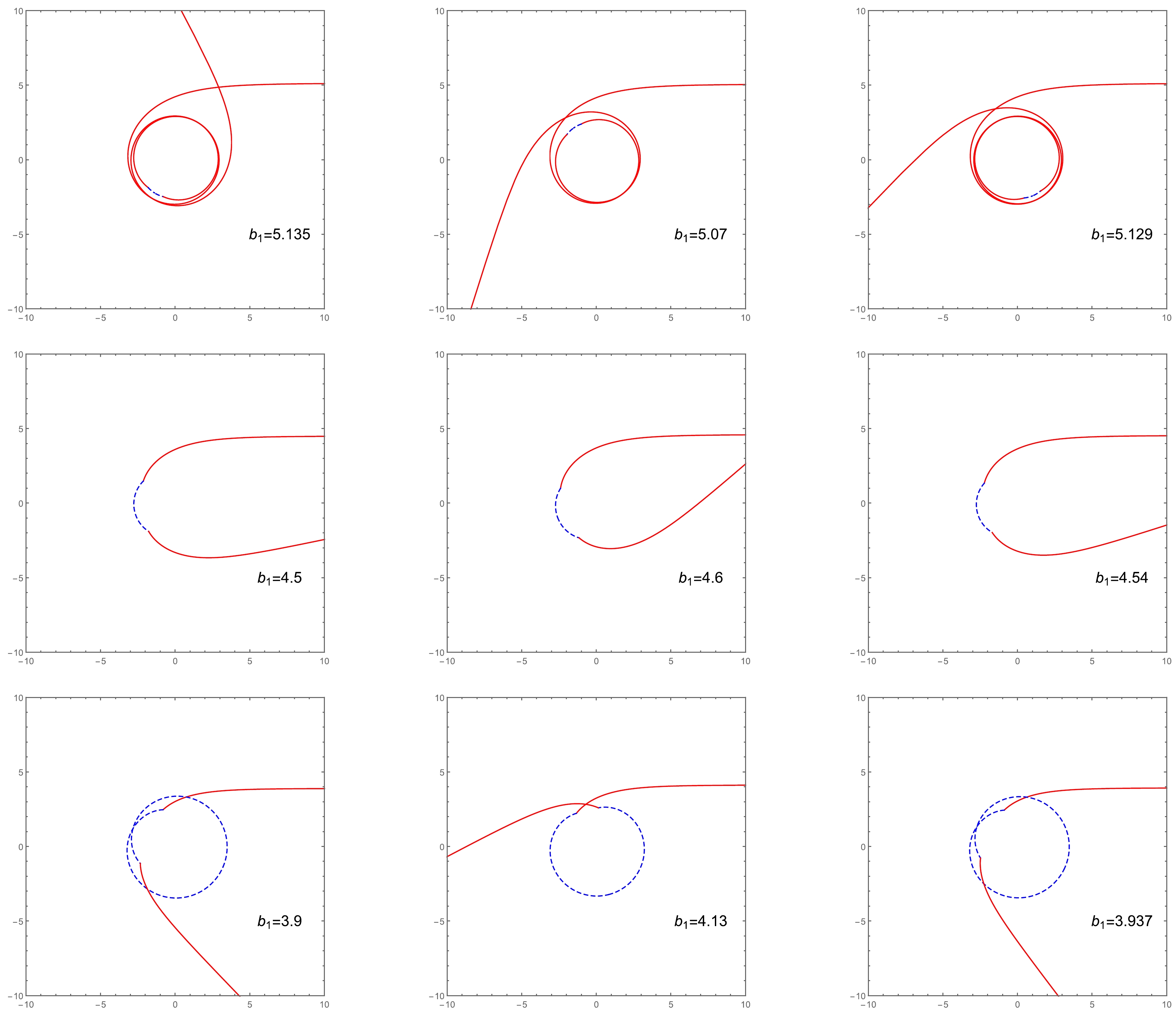
Figure 3. (color online) Trajectory of photons around an ATSW with impact parameters in the range (
$ A \cdot b_{c2} < b_{1} < b_{c1} $ ). The red and blue curves correspond to light trajectories in$ M_{1} $ and$ M_{2} $ , respectively. The left, middle, and right columns correspond to the choices ($ \Omega = 0.1, \gamma = 0.1 $ ), ($ \Omega = 0.2, \gamma = 0.1 $ ), and ($ \Omega = 0.1, \gamma = 0.4 $ ), respectively. The first, second, and third columns represent light ray trajectories with different impact parameters by fixing Ω and γ.From Fig. 3, it is evident that when the impact parameter
$ b_1 $ is smaller, the photon trajectories in$ M_1 $ become increasingly fewer, whereas the corresponding trajectories in$ M_2 $ increase. We also find that the trajectory (the motion of photon) is closely related to the parameter Ω, but is barely influenced by γ.In Fig. 4, the dashed and solid lines correspond to the light trajectories in
$ M_1 $ and$ M_2 $ , respectively. Case 1 (black lines): When$ b>b_{c1} $ , the photons from$ M_1 $ pass the vicinity of the throat and are reflected to the infinity of$ M_1 $ by the potential barrier. Case 2 (red lines): When$Ab_{c2} < b_1 <b_{c1}$ , the photons in$ M_1 $ enter$ M_2 $ through the throat and are then reflected back to$ M_1 $ by the potential barrier of$ M_2 $ . Finally, these photons reach the infinity of$ M_1 $ . Case 3 (green lines): When$ b_1<b_{c1} $ , the photons also fall into the throat and arrive at$ M_2 $ . However, when they pass through the photon sphere in$ M_2 $ at point F, they never return to$ M_1 $ . Instead, these photons are emitted to the infinity of$ M_2 $ . After obtaining the photon trajectories in the RGI-ATSW, we study the transfer function and optical appearance of this ATSW, as shown in next section. -
According to the definition proposed in [12], the trajectories of light can be divided into three branches:
$ 1) $ Direct emission$ (n>1/4) $ : The trajectories intersect with the accretion disk just once.$ 2) $ Lensing ring$ (n>3/4) $ : The trajectories intersect with the thin accretion disk twice.$ 3) $ Photon ring$ (n>5/4) $ : The trajectories intersect with the thin accretion disk at least three times.Here, n is the total number of orbits. Meanwhile, the photons obtain the additional luminosity from the thin accretion disk in each intersection. As described in the previous section, the study of orbit numbers and transfer functions in ATSWs are more complex than in the black hole case. Therefore, there are several obvious differences in the ATSW case. For simplicity, in this study, we only consider the thin accretion disk located at spacetime
$ M_1 $ , which is sufficient for the purpose of this study. For an observer located at the North Pole, the orbit numbers are redefined as$\begin{aligned}[b]& n_{1} = \dfrac{\varphi_{1} (b_{1})}{2\pi},\quad n_{2} = \dfrac{\varphi_{1}^* (b_{1})+\varphi_{2} (b_{1}/A)}{2\pi},\\& n_{3} = \dfrac{2\varphi_{1}^* (b_{1})+\varphi_{2} (b_{1}/A)}{2\pi}.\end{aligned} $

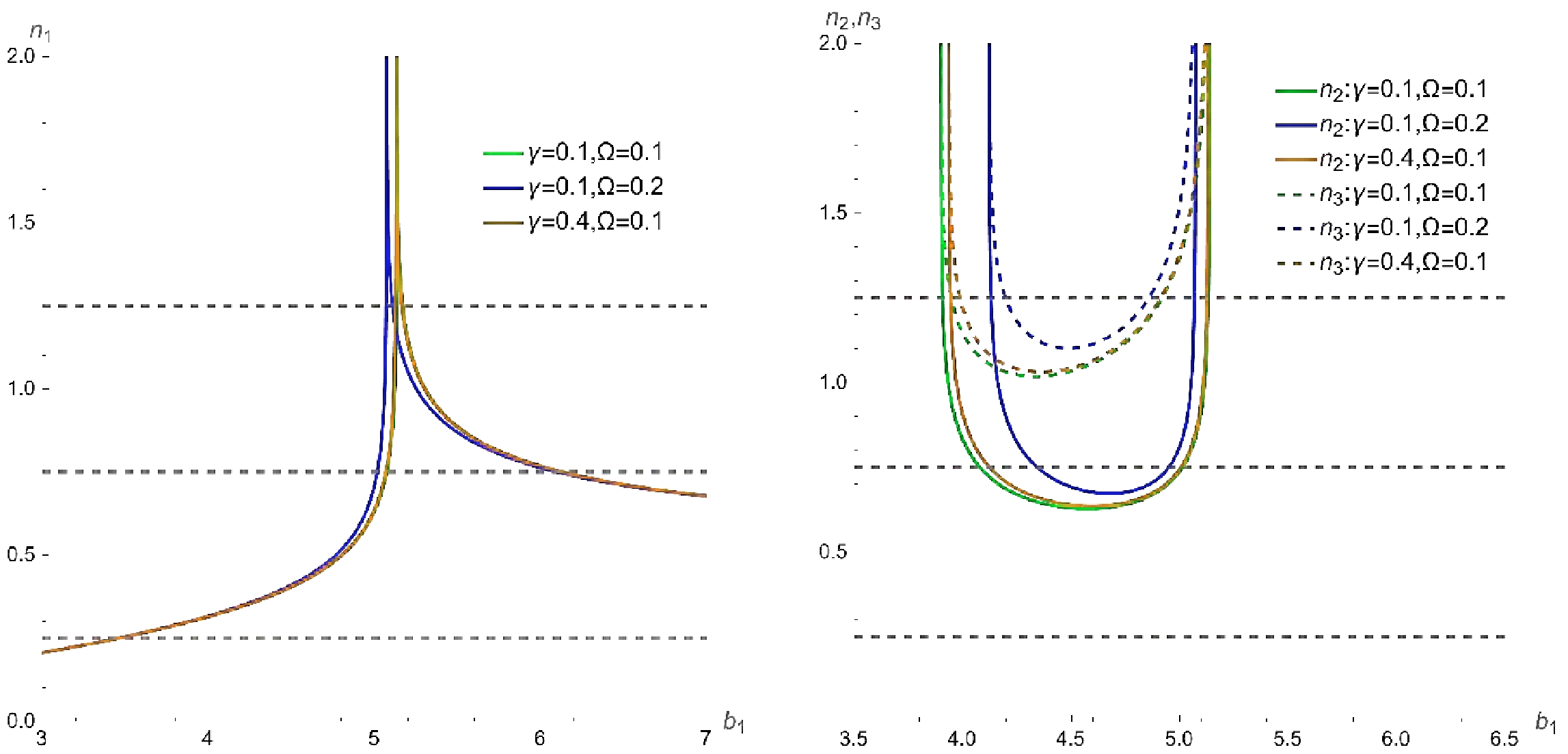
(13) Similar to the black hole case, we can also obtain the relationship between the orbit numbers and impact parameters using Eq. (13). To intuitively present this relationship, we plot Fig. 5.
As shown in Fig. 5, the number of orbits
$ n_1 $ in$ M_{1} $ is similar to that of the RGI black hole, as mentioned at the beginning of this section, i.e., 1)−3), and the number of orbits$ n_{2} $ and$ n_{3} $ only appear in the ATSW model. In addition, we find that Ω has a greater influence on$ n_1 $ ,$ n_2 $ , and$ n_3 $ comparing to γ. When$ n_{2}<3/4 $ and$ n_{3}>3/4 $ , the emitted/outgoing rays intersect with the disk at the front/back side. When$ n_{2}<5/4 $ and$ n_{3}>5/4 $ , the outgoing rays intersect with the disk at the front side. To obtain the observable appearance, we further study the transfer function in the ATSW.For simplicity, we consider a geometrically and optically thin accretion disk on the equatorial plane of
$ M_{1} $ , and the photon emitted from the accretion disk is assumed to be isotropic in the static observer's rest coordinate system. The emitted intensity$ I_{e} $ depends on the radial coordinate of the disk, the emission frequency of which is$ v_{e} $ . The observer is located at the North Pole and receives the specific intensity$ I_{o} $ with a redshift frequency, i.e.,$ v_{o} = \sqrt{F(r)}v_{e} $ . Following Liouville's theorem,$ I_{e}/v_{e}^3 $ is conserved along a light ray, which yields$ \dfrac{I_{e}}{v_{e}^{3}} = \dfrac{I_{o}}{v_{0}^{3}}, $

(14) and the specific intensity can be written as
$ I_{o} = F^{3/2}(r)I_{e}(r). $

(15) The total observed intensity can be obtained by integrating
$ I_{o} $ ,$ \begin{aligned}[b] I_{obs} =\;& \int I_{o}{\rm d} v_{e}= \int F^{3/2}(r)I_{e}(r) {\rm d} (\sqrt{F(r)}v_{e})\\ =\;& \int F^{2}(r) I_{e} {\rm d} v_{e} = \int F^{2}(r)I_{\rm emit}, \end{aligned} $

(16) where the total radiation intensity of the accretion disk is represented by
$I_{\rm emit} = I_{e}{\rm d} v_{e}$ . As discussed above, the total observed flux intensity can be found as$ I_{\rm obs}(b_1) = \sum\limits_{n} I_{\rm emit}F^{2}(r)\big|_{r = r_{n}(b_1)}, $

(17) where
$ r_{n}(b_1) $ is the transfer function, which represents the radial coordinate of the n-th intersection between the light ray with$ b_1 $ and the disk. Thus, the transfer function depends on the total number of orbits and the impact parameters. The slope of the transfer function, i.e.,${\rm d} r_n(b_1)/ {\rm d}b_1$ , is defined as the demagnified factor [12]. The first transfer function is essentially the redshift of the source profile with the minimum average slope, which is a dominant part of the observed intensity. It corresponds to the ''direct emission.'' The average slope of the second transfer function is between that of the first and third transfer functions and provides a highly demagnified image of the thin disk on the backside. It contributes a small part to the observed intensity, which corresponds to the ''lensing ring.'' The average slope of the third transfer function is the largest, which gives an extremely demagnified image of the disk on the front side. In general, it corresponds to the “photon ring.” In Fig. 6, we show the transfer functions$ r_{n}(b_1) $ as a function of impact parameter$ b_1 $ .
Figure 6. (color online) Transfer functions for different choices of parameters in RGI-ATSW spacetime. The black, orange, and red curves represent the first, second, and third transfer functions, respectively.
As shown in Fig. 6, there are two new third transfer functions that appear near
$ A \cdot b_{c2} $ and$ b_{c1} $ in the ATSW. The absolute slopes of these two third transfer function are almost at the same level as that of the conventional third transfer function near$ b_{c1} $ (red line on the right side of$ b_{c1} $ ). A new second transfer function appears between$ A \cdot b_{c2} $ and$ b_{c1} $ , which is the orange line in Fig. 6, and its average slope is moderate. Combining the above facts, it is interesting that the subsequent additional light rings evidently originate from these transfer functions, which is a feature not exhibited by black holes. In addition, the result shows that the second and third transfer functions clearly change when the parameter Ω increases, whereas the change caused by γ is relatively small.To investigate the optical appearance of the RGI-ATSW, the emitted model of the thin disk is established next. In general, we choose Model 1 as
$ {I_{\rm emi{t_1}}} = \left\{ {\begin{array}{*{20}{l}} 0&{ r < {r_{\rm isco}}}\\ {}&{}\\ {{{\rm e}^{ - (r - {r_{\rm isco}})}}}&{r \ge {r_{\rm isco}}} \end{array},} \right. $

(18) where
$r_{\rm isco}$ is the innermost stable circular orbit in$ M_{1} $ . For the spherically symmetric spacetime,$r_{\rm isco}$ can be expressed as [57]$ r_{\rm isco} = \frac{3f(r_{\rm isco})f'(r_{\rm isco})}{2f'(r_{\rm isco})^2-f(r_{\rm isco})f''(r_{\rm isco})} . $

(19) The emission peak value reaches its maximum value at
$r = r_{\rm isco}$ and then rapidly decays with r. For Model 2, we choose$ {I_{\rm emi{t_2}}} = \left\{ {\begin{array}{*{20}{l}} 0&{ r < {r_p}}\\ {}&{}\\ {\dfrac{{\dfrac{\pi }{2} - \arctan(r - 5)}}{{\dfrac{\pi }{2} - \arctan( - {r_p})}}}&{r \ge {r_p}} \end{array}.} \right. $

(20) In Model 2, the emitted function decays more slowly, and the emission peak value reaches its maximum value at
$ r = r_{p} $ in$ M_1 $ . The corresponding emission functions are shown in Fig. 7.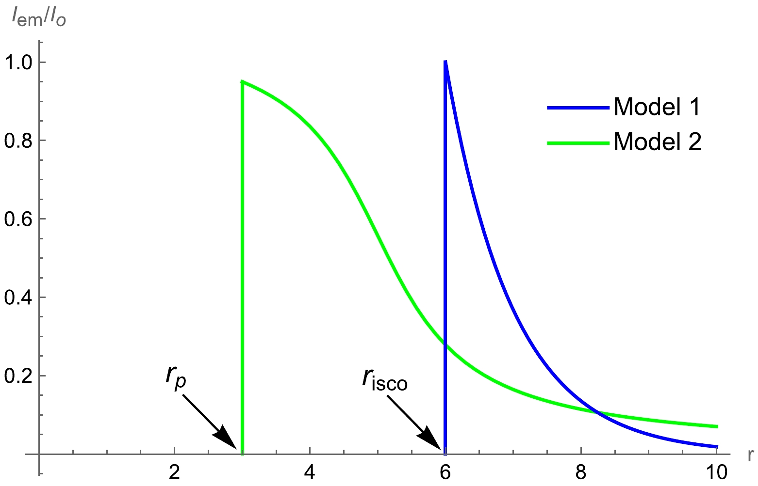
Figure 7. (color online) Emitted functions for different models, where the blue and green curves represent Models 1 and 2, respectively.
The total observed intensity can be obtained using Eq. (17), which we plot as a function of the impact parameter. For Models 1 and 2, the observed intensity and corresponding 2-dimensional images of the RGI-ATSW are shown in Figs. 8 and 9, respectively.
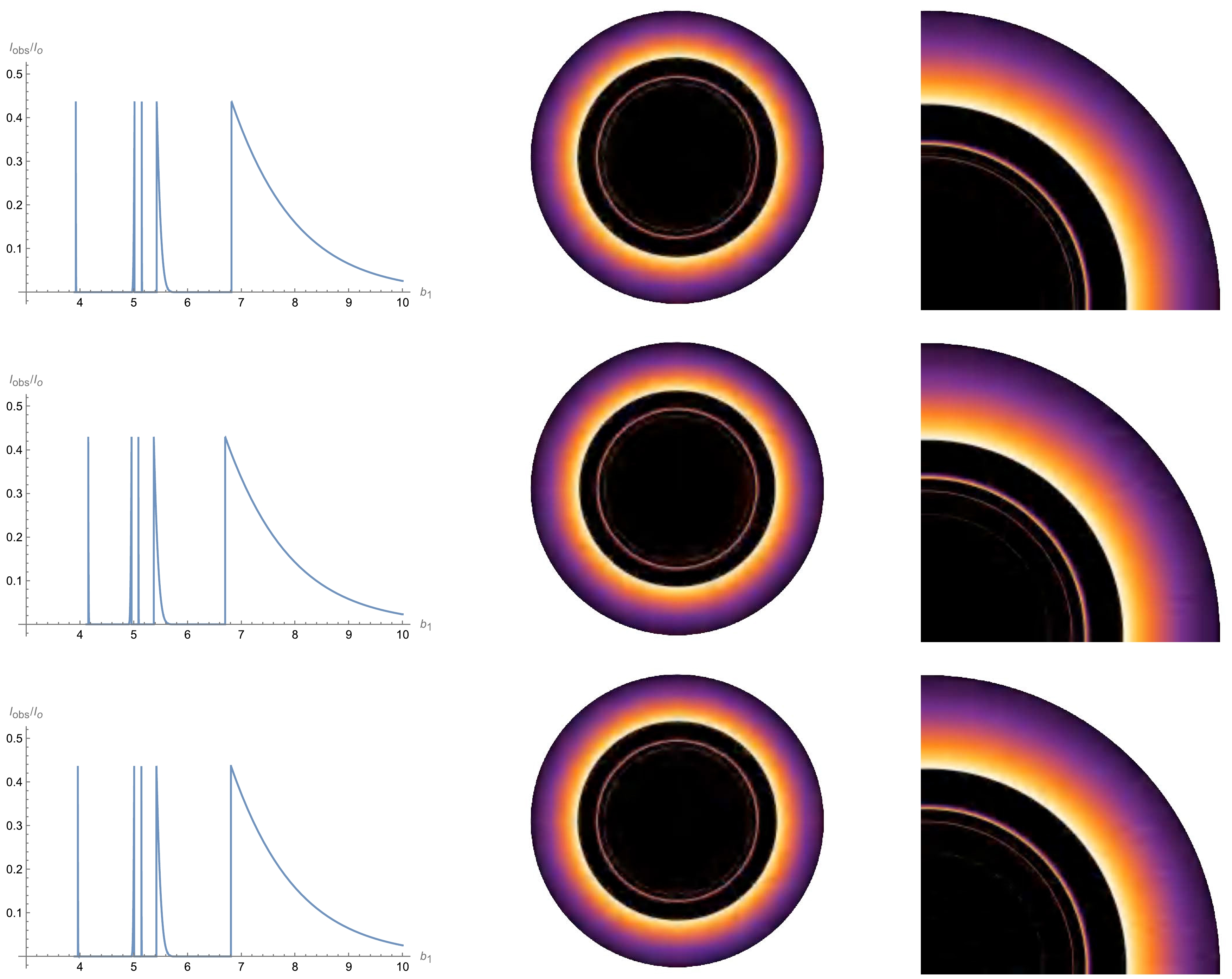
Figure 8. (color online) In the context of the RGI-ATSW, three set values of parameters Ω and γ are used to obtain the observed total flux for Model 1, the corresponding 2-dimensional shadow graphs, and local zoom-in detail of the shadow graphs. The first row corresponds to
$ \Omega = 0.1, \gamma = 0.1 $ , the second row is$ \Omega = 0.2, \gamma = 0.1 $ , and the last row represents$ \Omega = 0.1, \gamma = 0.4 $ .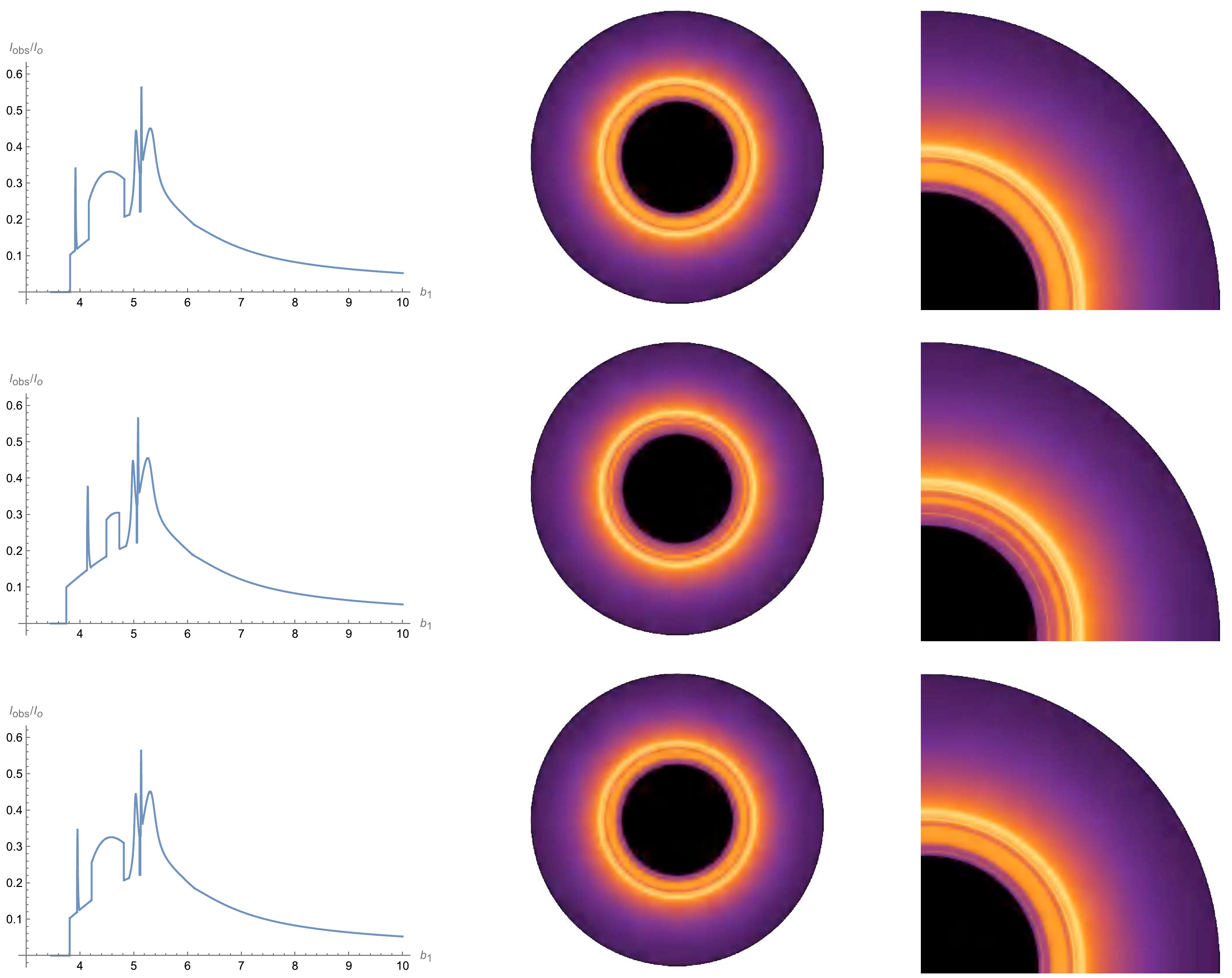
Figure 9. (color online) Taking the same choices of Ω and γ as in Fig. 8, the observable appearance for Model 2, including the observed total flux, corresponding 2-dimensional shadow graphs, and local zoom-in details of the shadow graphs.
The first row of Fig. 8 shows that when the impact parameter increases, there are five peaks, which correspond to the three photon rings, lensing ring, and direct emission, from left to right. The photon and lensing rings exactly match the third and second transfer functions. In particular, the first and second rings are the additional photon rings in the RGI-ATSW that the black hole does not have, which correspond to the additional third transfer functions. The middle and right panels display 2-dimensional ATSW images and their local enlargement images. Furthermore, at the same parameters levels, the effect of Ω is more obvious than that of γ. As Ω increases, the first photon ring becomes increasingly larger, whereas the second and third photon rings along with the lensing ring and direct emission all become smaller, forming a more tightly arranged overall ring structure. γ appears to have a similar behavior to Ω; however, its effect is very small. Meanwhile, the total observable luminosity is mainly composed of direct emission, and the contribution of photon and lensing rings is small. Even so, the additional rings of the ATSW might also be observable in the future. Interestingly, images of the well-known Ellis-Bronnikov (EB) wormhole were studied in Ref. [58] by considering the thin accretion disk, where only one photon ring was located at one side of the wormhole throat. Comparing our work with Ref. [58], several differences are found between the results of this study and Ref. [58]. First, we use the asymmetric thin-shell wormhole improved by the renormalization group, whereas Huang et al. used an EB wormhole, which is the solution to Einstein-free scalar theory. Second, in Ref. [58], only one side of the EB wormhole possessed a photon ring. However, in our study, we consider the RGI-ATSW to possess a photon ring on both sides of the throat. Finally, Ref. [58] not only considered the observer located at the side on which the accretion disk was located, but also the other side of throat. Owing to these differences, Ref. [58] found that the wormhole observed on the side of the spacetime with the photon ring appeared similar to that for a black hole, unlike that observed in our study because no photons return from the throat. The observations on the other side also differed from those in our study because there was no direct emission of the disk in Ref. [58].
For emission Model 2, the images of the RGI-ATSW are shown in Fig. 9. In the range
$ 4.2<b_1<4.8 $ for the leftmost plot of the first row, note that there is a new wide hump, which is the contribution of the new second transfer function to the observed flux. In this model, there are still two new photon rings, which also originate from two new third transfer functions. Similar to Model 1, the parameter Ω has the more obvious effect on the observed intensity compared to γ. In contrast to Model 1, the observed light rings are more complex and can be used to distinguish the RGI-ATSW from the RGI black hole and Schwarzschild-TSW. To intuitively present the differences in the observed images of the RGI-ATSW, RGI black hole, and Schwarzschild-TSW, we plot Fig. 10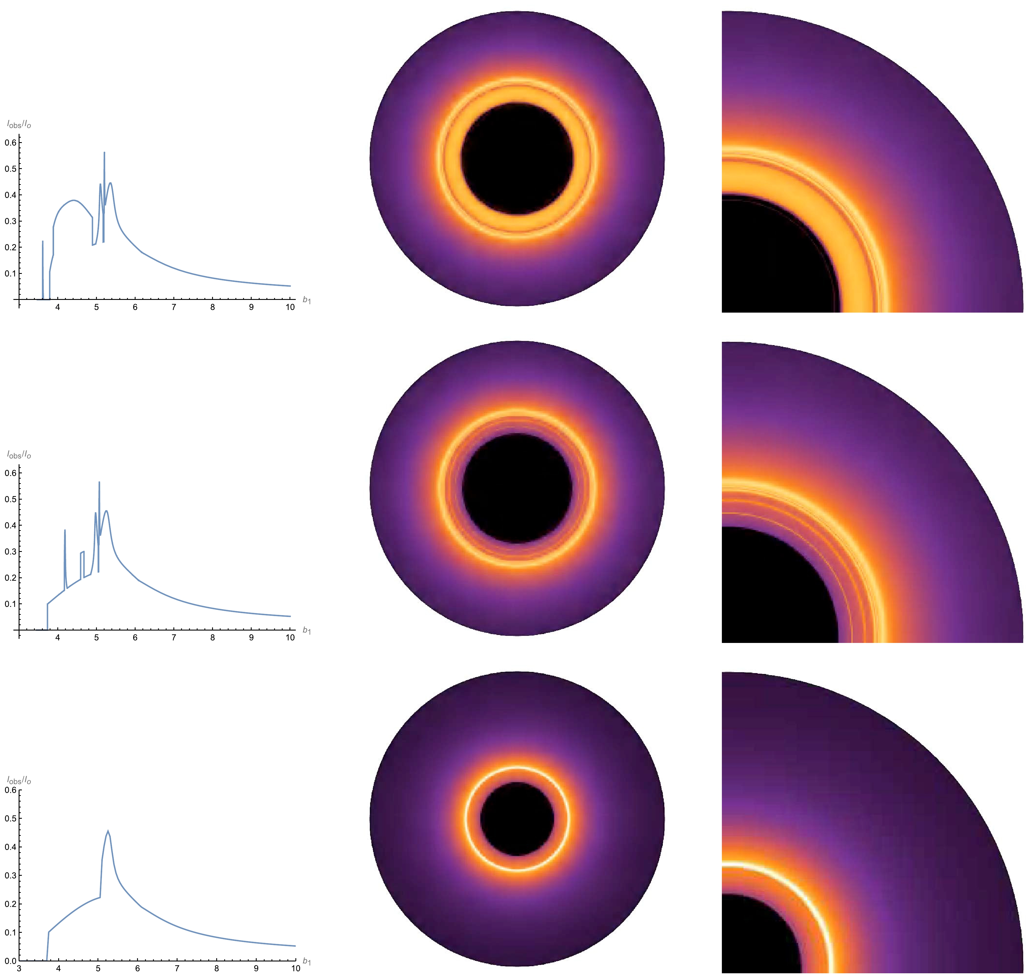
Figure 10. (color online) Each row from top to bottom corresponds to a Schwarzschild-ATSW, RGI-ATSW, and RGI black hole for Model 2, where
$ \Omega = 0.2 $ and$ \gamma = 0.3 $ are selected in the RGI spacetime. We also choose the same parameters for the Schwarzschild-ATSW, i.e., R,$ M_1 $ , and$ M_2 $ .We also show the thin disk appearance of the Schwarzschild wormhole, RGI wormhole, and black hole with the RGI parameters set to
$ \Omega = 0.2 $ and$ \gamma = 0.3 $ under emission Model 2, as shown in Fig. 10.In Fig. 10, for the RGI-ATSW, the results show that the photon rings are all superimposed on the direct emission, including the lensing ring. However, for the Schwarzschild-ATSW, not all rings overlap on the direct emission, i.e., the first additional ring of the leftmost image. Moreover, the additional lensing hump in the RGI-ATSW is considerably narrower than that of the Schwarzschild-ATSW. For the black hole, there are no additional photon rings and lensing humps, and the usual rings and direct emission all overlap and cannot be distinguished from each other. From the above results, the observed image of the RGI-ATSW possess more abundant multi-ring structures compared with the RGI black hole and Schwarzschild-ATSW. Therefore, we conclude that when a thin accretion disk exists around an ATSW, observations of the RGI-ATSW can help further distinguish it from Schwarzschild-ATSWs and RGI black holes.
-
In this study, by considering a thin accretion disk around an ATSW, we investigate the trajectory and deflection angle of photons in the RGI-ATSW and then obtain the observed images. We assume that the observer is located at
$ M_{1} $ and consider the thin accretion disk to be placed on the equatorial plane. In a black hole, the photons with$ b<b_c $ are absorbed by the black hole and hence can never escape. However, in the case of the ATSW, some photons that fall into the photon sphere may travel through the throat under certain conditions and then turn back to the initial spacetime$ M_{1} $ . Thus, these photons can be captured by the observer, contributing to the final observed images. Based on this fact, we calculate the orbit number n and the trajectories of photons with the aid of the deflection angle. Considering that the photons would obtain the additional luminosity from the disk at each intersection, we further study the transfer function in the RGI-ATSW. Finally, the optical appearances of the RGI-ATSW are obtained by considering two different emission models.For the RGI-ATSW, the results show that the orbit number n is no longer the same as that of a black hole and has two new orbit numbers because the photons can return to
$ M_{1} $ . The corresponding trajectories of the photons around the ATSW with impact parameters in the range ($ A \cdot b_{c2} < b_{1} < b_{c1} $ ) show that as the impact parameter decreases, the photons remain for longer at$ M_2 $ . For the transfer function, there is a new second and two new third transfer functions not exhibited by the black hole does. For the optical appearance of the RGI-ATSW shown in Fig. 8, there are five peaks in Model 1, which correspond to the three photon rings, lensing ring, and direct emission, from left to right. The first and second rings are the additional photon rings in the RGI-ATSW, corresponding to the additional third transfer functions. For Model 2, a new wide hump appears between the first and second additional photon rings, which is the contribution of the new second transfer function to the observed flux. These photon and lensing rings and the wide hump all superimpose on direct emission. Furthermore, we study the effects of Ω and γ on the observable appearance of the RGI-ATSW and find that Ω is more important because its influences on the orbit numbers, photon trajectories, transfer functions, and observable appearance are more evident compared to those of γ. In addition, we compare the observable appearance of the RGI-ATSW with that of a Schwarzschild-ATSW and RGI black hole and find that the observed image of the RGI-ATSW possesses more abundant multi-ring structures, which might be observed in future. Therefore, we conclude that when a thin accretion disk exists around an ATSW, the observations of the RGI-ATSW can help further distinguish it from other ATSWs and black holes.
Additional observational features of the thin-shell wormhole by considering quantum corrections
- Received Date: 2024-08-04
- Available Online: 2024-12-15
Abstract: By considering an asymmetric thin-shell wormhole (ATSW) surrounded by an optically and geometrically thin disk, we investigate the luminosity distribution of this ATSW with the spacetime on two sides encoded with the renormalization group improved (RGI) parameters (Ω, γ). Although some light rays are absorbed into the throat in the vicinity of the wormhole, they return through the throat with certain conditions, unlike in the case of black holes. The spacetime on one side of the wormhole can capture the additional photons emitted from the thin disk, resulting in several interesting observable features of the wormhole. The results in this paper show that there are two additional orbit numbers n in the ATSW and six transfer functions, rather than three as in the black hole case. In this case, the ATSW indeed has a more complex observable structure, where some additional light rings arise naturally. For instance, there are two additional photon rings for the emitted Model 1. Moreover, we also find a new wide hump between the first and second additional photon rings in Model 2. The effects of Ω and γ on the observed images are clearly addressed throughout this study, and the influence of Ω is found to be larger. Finally, we conclude that the observations of the RGI-ATSW can help further distinguish it from other ATSWs and black holes when a thin accretion disk exists around it.


 Abstract
 HTML
HTML Reference
 Related
 PDF
PDF




 DownLoad: